Double-reinforced type crane girder lengthening device

A reinforced, crane technology, used in cranes and other directions, can solve problems such as hidden safety hazards and insufficient structural strength, and achieve the effects of stable box structure, high force strength and space saving.

Inactive Publication Date: 2016-04-06
ANHUI CHAOSHENG HOISTING MACHINERY CO LTD
View PDF1 Cites 8 Cited by
  • Summary
  • Abstract
  • Description
  • Claims
  • Application Information

AI Technical Summary

Problems solved by technology

[0003] Chinese patent CN204873627U discloses a crane girder extension device, which includes a fixed beam and a moving beam, a telescopic oil cylinder is installed on the upper side of the fixed beam, a piston rod is arranged in the telescopic oil cylinder, and a second weight reduction device is provided on the left and right side walls of the fixed beam Holes, roller grooves are symmetrically arranged inside the left and right side walls of the fixed beam, the left end of the moving beam is arranged inside the fixed beam, support rollers are symmetrically arranged on the left and right side walls of the moving beam, and the left and right side walls of the moving beam are provided with The first weight-reducing hole, the top of the moving beam is provided with a support device, the top of the right end of the moving beam is provided with a fixed frame, the fixed frame is connected with the top of the piston rod, the bottom of the moving beam is welded with I-beam, and an electric hoist is installed on the I-beam , the right end of the fixed beam is provided with a safety hook; the invention has the advantages of reasonable design, simple structure, convenient use, large working area, high working efficiency, good lifting performance, long service life, stable operation, safety and reliability, but during use Among them, the structural strength of this invention is insufficient, and there are potential safety hazards, which need to be improved urgently

Method used


Image

  • Double-reinforced type crane girder lengthening device
  • Double-reinforced type crane girder lengthening device

Examples


Embodiment Construction

[0013] The technical solution of this patent will be further described in detail below in conjunction with specific embodiments.

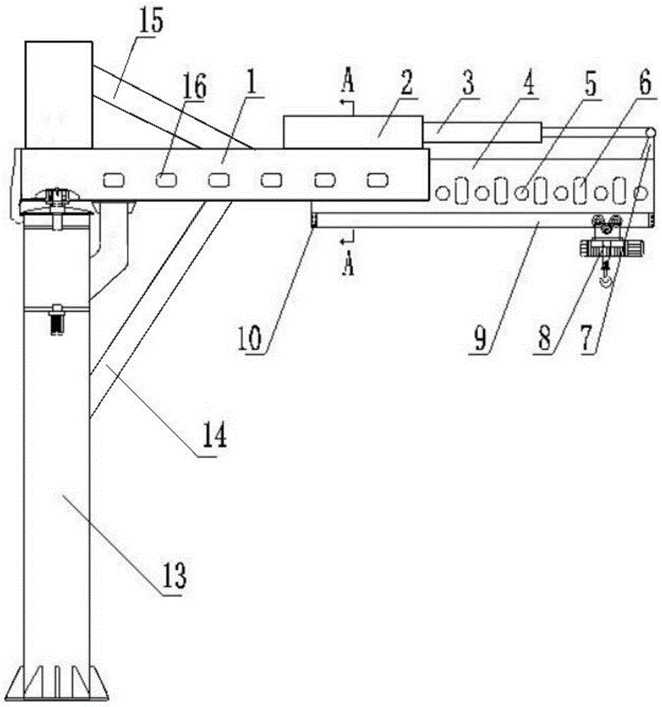
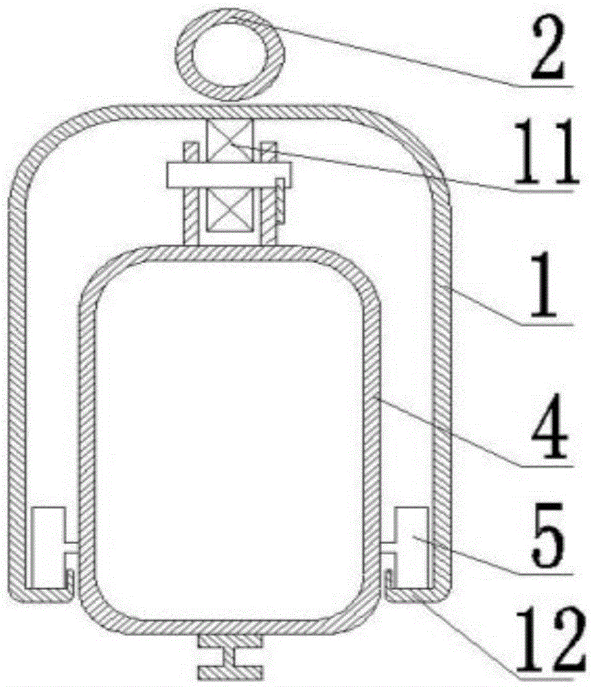
[0014] see Figure 1~2 , a double-reinforced crane girder extension device, including a fixed beam 1 and a movable beam 4, a telescopic oil cylinder 2 is installed on the upper side of the fixed beam 1, and a piston rod 3 is arranged in the telescopic oil cylinder 2, and the fixed The left and right side walls of the beam 1 are provided with second weight-reducing holes 16, and the left and right side walls of the fixed beam 1 are respectively symmetrically provided with roller grooves 12, and the left end of the moving beam 4 is arranged on the fixed beam 1. Inside, the left and right side walls of the moving beam 4 are respectively symmetrically provided with support rollers 5, the left and right side walls of the moving beam 4 are provided with first lightening holes 6, and the top of the moving beam 4 is provided with a support Device 11, the ...


PUM


Abstract

The invention discloses a double-reinforced type crane girder lengthening device which comprises a fixed beam and a movable beam. A telescopic cylinder is mounted on the upper side face of the fixed beam, and a piton rod is arranged in the telescopic cylinder. Second lightening holes are formed in the left side wall and the right side wall of the fixed beam, and rolling wheel grooves are symmetrically formed in the left side wall and the right side wall of the fixed beam. A fixing frame is arranged on the top of the right end of the movable beam and connected with the top end of the piston rod, I steel is welded at the bottom end of the movable beam, and an electric hoist is mounted on the I steel. A safety hook is arranged at the right end of the fixed beam and connected with a stand column, and the stand column penetrates through the fixed beam and extends to the position above the fixed beam. A first oblique rod is arranged under the fixed beam, and a second oblique rod is arranged above the fixed beam. According to the double-reinforced type crane girder lengthening device, the structure strength of a whole girder is improved.

Description

technical field [0001] The invention relates to the technical field of cranes, in particular to a double-reinforced crane girder extension device. Background technique [0002] In recent years, with the rapid development of industrial technology and logistics trade, the development of cranes as important logistics machinery is getting faster and faster, and the requirements for cranes are getting higher and higher. The length of the girder of the existing cranes is generally a certain Yes, this limits the working range of the crane and affects the working efficiency of the crane. Therefore, it is of great significance and effect to design a reasonable design, simple structure, convenient installation and maintenance, light weight, wide working range, strong lifting capacity, high work efficiency, safe and stable crane girder extension device. [0003] Chinese patent CN204873627U discloses a crane girder extension device, which includes a fixed beam and a moving beam, a tele...

Claims


Application Information

Patent Timeline
Patent Type & Authority Applications(China)
IPC IPC(8): B66C23/693
CPCB66C23/68
Inventor 王云祥
Owner ANHUI CHAOSHENG HOISTING MACHINERY CO LTD
Why Eureka
Try Eureka