
Novel axial flow turbine suitable for pulse pressure charging

A technology of axial flow turbine and pulse supercharging, which is applied in the direction of mechanical equipment, engine components, combustion engines, etc., can solve the problems of starting loss, long flow channel, low flow rate, etc., and achieve the reduction of mixing loss, improvement of efficiency, and transient speed up the effect

Inactive Publication Date: 2016-04-06
CHINA NORTH ENGINE INST TIANJIN
View PDF5 Cites 2 Cited by
  • Summary
  • Abstract
  • Description
  • Claims
  • Application Information

AI Technical Summary

Problems solved by technology

[0003] 1. Under the condition of pulse intake, the volute has an unsteady effect due to its long flow path and low flow velocity (compared to the rotor), which causes the rotor inlet condition to be uneven along the circumference and change with time. Pressure, temperature and fluid velocity are no longer in sync
[0004] 2. Because the inlet conditions of each blade channel of the rotor are not uniform, the outlet conditions are no longer uniform, which leads to the homogenization of fluid mixing downstream of the rotor outlet, resulting in start-up loss
[0005] 3. Since the characteristic quantities of the flow are not synchronized in time, the mass flow rate of the turbine is no longer synchronized with the turbine expansion ratio
Therefore, the high-efficiency region of the turbine is no longer synchronized in time with the high-flow region, so that the efficiency of the turbine is lower than that of the steady and quasi-steady state

Method used


Image

  • Novel axial flow turbine suitable for pulse pressure charging
  • Novel axial flow turbine suitable for pulse pressure charging
  • Novel axial flow turbine suitable for pulse pressure charging

Examples


Embodiment Construction

[0033] It should be noted that, in the case of no conflict, the embodiments of the present invention and the features in the embodiments can be combined with each other.

[0034] In describing the present invention, it should be understood that the terms "center", "longitudinal", "transverse", "upper", "lower", "front", "rear", "left", "right", " The orientations or positional relationships indicated by "vertical", "horizontal", "top", "bottom", "inner" and "outer" are based on the orientations or positional relationships shown in the drawings, and are only for the convenience of describing the present invention and Simplified descriptions, rather than indicating or implying that the device or element referred to must have a particular orientation, be constructed and operate in a particular orientation, and thus should not be construed as limiting the invention. In addition, the terms "first", "second", etc. are used for descriptive purposes only, and should not be understood ...


PUM

PropertyMeasurementUnit
Angleaaaaaaaaaa

Abstract

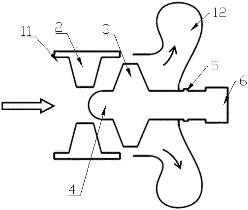
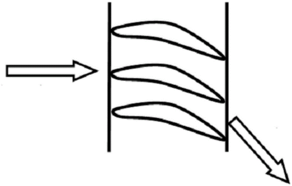
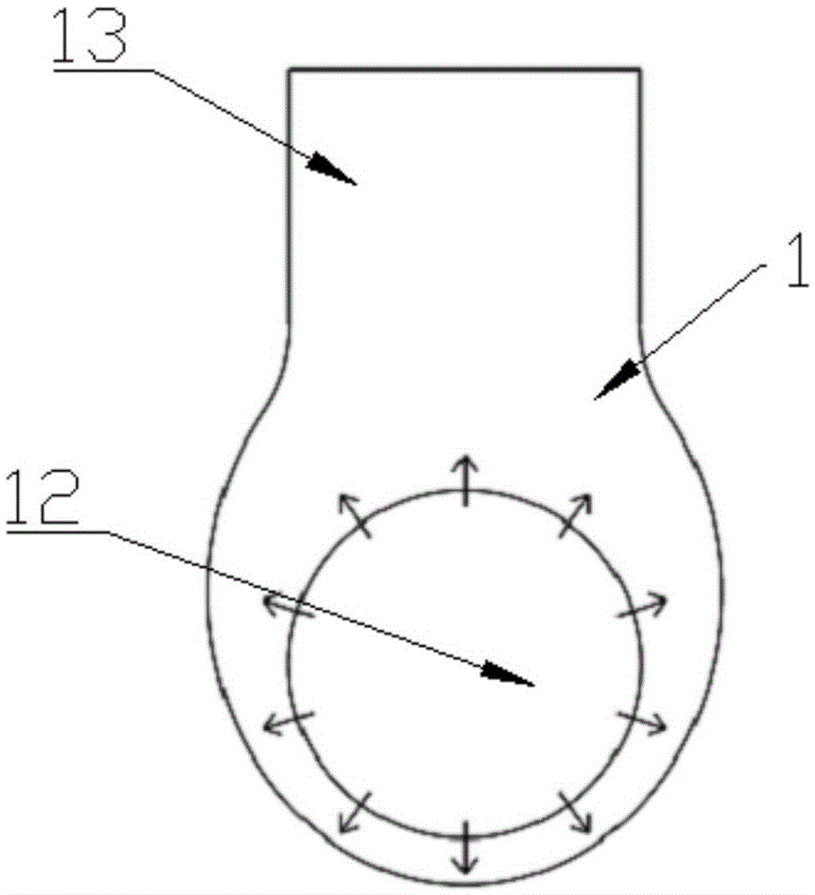
The invention provides a novel axial flow turbine suitable for pulse pressure charging. The novel axial flow turbine comprises a volute, stators, a rotor, a rotating shaft, a seal ring and a bearing. A gas inlet is formed in the front end of the volute, and a pressure expander is arranged at the rear end of the volute. An exhaust port is fixedly formed in the upper end of the pressure expander. The stators are each in an annular shape and located on the inner wall of the gas inlet of the volute. The front end of the rotating shaft is in an arc shape and located on the portion, close to the rear side, between the stators. The rear end of the rotating shaft is fixed to the rear side wall of the volute through the bearing. The rotor is fixed to the portion, close to the front end, on the rotating shaft. The front end of the pressure expander is located on the rear side of the rear side wall of the rotor. According to the novel axial flow turbine suitable for pulse pressure charging, work of the stators and work of the rotor are closer to the quasi-steady state, and therefore the efficiency of the rotor is improved; and in addition, flowing at the outlet of the rotor is uniform in the circumferential direction, and the mixing loss generated on the downstream part of the rotor due to circumferential-direction ununiformity is also reduced to some extent.

Description

technical field [0001] The invention belongs to the technical field of exhaust gas turbocharging, and in particular relates to a novel axial-flow turbine suitable for pulse supercharging. Background technique [0002] Pulse supercharging utilizes the energy of the pulse exhaust of the internal combustion engine to increase the work output of the turbocharger turbine. The commonly used radial flow, mixed flow and axial flow all use volutes to distribute the exhaust gas of the internal combustion engine to the circumference of the turbine rotor. This method is not conducive to fully utilizing the energy of the pulse, the reason is that the efficiency of the rotor decreases, the specific details are as follows: [0003] 1. Under the condition of pulse intake, the volute has an unsteady effect due to its long flow path and low flow velocity (compared to the rotor), which causes the rotor inlet condition to be uneven along the circumference and change with time. Pressure, temper...

Claims


Application Information

Patent Timeline
IPC IPC(8): F01D1/04F01D9/04F02B37/00
CPCF01D1/04F01D9/04F02B37/00F05D2220/40Y02T10/12
Inventor 邢卫东陈化佟鼎刘莹黄磊马磊
Owner CHINA NORTH ENGINE INST TIANJIN
Learn More