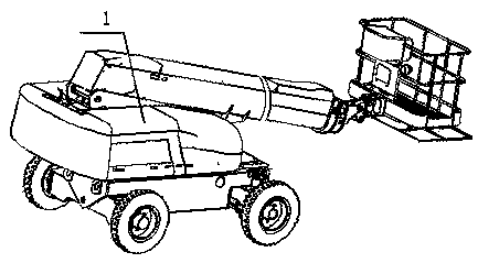
A power cabin structure and an aerial work platform using the structure
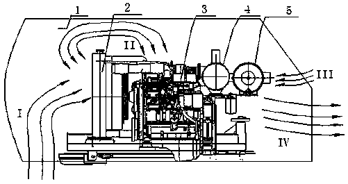
A power compartment and cold air technology, applied in the cooling of the engine, engine components, machines/engines, etc., can solve the problems of engine 3 power drop, engine 3 intake temperature rise, and affect combustion efficiency, etc., to improve the intake air Pressure, the effect that is conducive to air intake
- Summary
- Abstract
- Description
- Claims
- Application Information
AI Technical Summary
Problems solved by technology
Method used
Image

Examples
Embodiment Construction
[0032] The present invention will be further described below in conjunction with accompanying drawing.
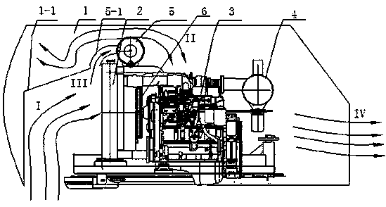
[0033] Among them, the present invention is attached image 3 as a basis, with image 3 The left, right, upper, lower, bottom, center, and inner cavities are left, right, upper, lower, bottom, center, and inner cavities of the present invention. It should be noted that the relative arrangement, numerical values, etc. of components set forth in the present embodiment are not limited to the scope of the present invention unless specifically stated otherwise.
[0034] Such as image 3 Shown: the present invention discloses a kind of power cabin structure, it comprises:
[0035] The wind deflector 1-1, radiator 2, air filter 5, engine 3 and muffler 4 are sequentially arranged in the power cabin;
[0036] The wind guide cover 1-1 communicates with the outside air and is arranged at the air inlet on the left side of the hood 1 and the air inlet surface of the radiator 2; the ...
PUM
 Abstract
Description
Claims
Application Information
 - R&D Engineer
- R&D Manager
- IP Professional
- Industry Leading Data Capabilities
- Powerful AI technology
- Patent DNA Extraction
Browse by: Latest US Patents, China's latest patents, Technical Efficacy Thesaurus, Application Domain, Technology Topic.
© 2024 PatSnap. All rights reserved.Legal|Privacy policy|Modern Slavery Act Transparency Statement|Sitemap