Double-effect vacuum tube bundle drying system

A tube bundle drying and vacuum technology, which is used in drying solid materials, drying gas layout, drying, etc.

Active Publication Date: 2016-04-06
郑州博大浓缩干燥设备有限公司
View PDF7 Cites 14 Cited by
  • Summary
  • Abstract
  • Description
  • Claims
  • Application Information

AI Technical Summary

Problems solved by technology

[0003]However, when using tube bundle dryers to dry materials, most of them use single-effect tube bundle drying systems, that is, one tube bundle dryer is used to dry materials. Moreover, the material is dried under normal pressure, and the heat required for drying the material is relatively large. Therefore, the heat source used by the existing tube bundle dryer is high-temperature raw steam, and the dried material may die due to excessive temperature. The scorching phenomenon occurs, which leads to the deterioration of the quality of the dried material, and the secondary steam generated after the water in the material evaporates contains a scorched smell. The generation of high-temperature raw steam requires a lot of fuel and consumes a lot of energy
[0004] In addition, the secondary steam generated by the existing tube bundle dryer when drying materials is directly discharged to the atmosphere, and a large amount of heat contained in the secondary steam is wasted, and the secondary steam Secondary steam contains dust and other pollutants, polluting the atmosphere
In addition, the raw steam used in the existing tube bundle dryer condenses into condensed water after heat exchange, and the condensed water still contains a lot of heat. Most of the condensed water produced by the existing tube bundle dryer is directly discharged, and the heat contained in the condensed water is absorbed waste, and direct discharge also causes waste of water resources, which does not meet the requirements of environmental protection and energy saving

Method used


Image

  • Double-effect vacuum tube bundle drying system

Examples


Embodiment Construction

[0028] The present invention will be further described in detail below in conjunction with the accompanying drawings.

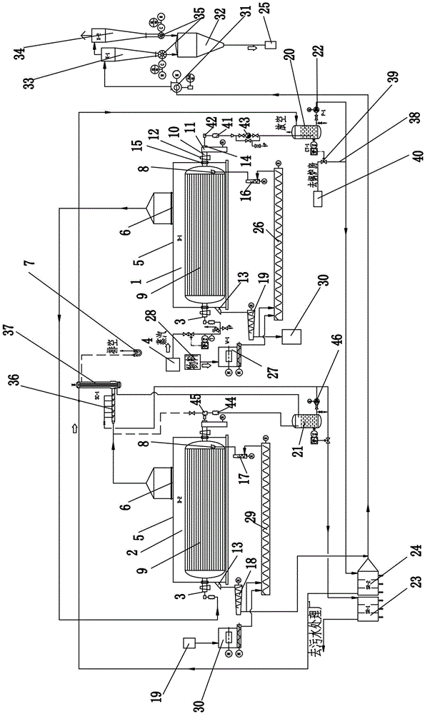
[0029] Such as figure 1As shown, a double-effect vacuum tube bundle drying system includes a first-effect tube bundle dryer 1 and a second-effect tube bundle dryer 2, and the first-effect tube bundle dryer 1 and the second-effect tube bundle dryer 2 have the same structure, both of which are sealed tube bundle dryers. Including housing 5, tube bundle 9, rotating shaft 10, transmission device 11, support device 12, feed inlet 8, discharge outlet 13, steam inlet 3, water outlet 14 and secondary steam outlet 6, the tube bundle 9 is set in Inside the casing 5, a rotating shaft 10 is provided at both ends of the tube bundle 9, and the rotating shaft 10 is movably connected with the casing 5 through a mechanical seal 15. The rotating shaft 10 outside the casing 5 is arranged on a supporting device 12, and the rotating shaft 10 is hollow Shaft, one end of the hous...


PUM


Abstract

The invention relates to a double-effect vacuum tube bundle drying system. The double-effect vacuum tube bundle drying system comprises a first-effect tube bundle drying machine and a second-effect tube bundle drying machine; the first-effect tube bundle drying machine and the second-effect tube bundle drying machine are both sealing tube bundle drying machines; secondary steam in shells of the two tube bundle drying machines is extracted through a vacuum pump; secondary steam in the first-effect tube bundle drying machine is conveyed to a steam inlet of the second-effect tube bundle drying machine, and serves as a heat source of drying of the second-effect tube bundle drying machine; a material dried by the first-effect tube bundle drying machine is fed in the second-effect tube bundle drying machine for secondary drying; and a heat source of secondary drying is secondary steam generated in the first-effect tube bundle drying machine. The double-effect vacuum tube bundle drying system performs two-stage double-effect gradient drying for the material, and continuously and gradiently uses the steam heat; the two tube bundle drying machines dry under vacuum condition to effectively reduce the needed drying temperature; waste steam and steam condensed water heat are recovered for further pneumatic drying; the heat is fully used; and the energy is saved.

Description

Technical field: [0001] The invention belongs to the technical field of drying equipment for loose materials such as powders and granules, and in particular relates to a double-effect vacuum tube bundle drying system. Background technique: [0002] At present, in the fields of starch industry and feed processing industry, when drying loose materials such as powder and granules, the drying equipment used is still the tube bundle dryer, which is an indirect heating contact dryer. The motor and reducer drive the tube bundle to rotate, and the material enters the dryer from the feed inlet through the feed auger, and the powder material is picked up by the lifting plate installed on the periphery of the tube bundle, and continuously pushed from the feed inlet to the outlet. At one end of the feed port, the material is picked up to the top by the lifting board and then falls into the tube bundle under the action of gravity. The high-temperature steam enters the tube bundle tube...

Claims


Application Information

Patent Timeline
Patent Type & Authority Applications(China)
IPC IPC(8): F26B17/20F26B21/00F26B25/00
CPCF26B17/20F26B21/002F26B25/00Y02P70/10
Inventor 孙发喜
Owner 郑州博大浓缩干燥设备有限公司
Why Eureka
Try Eureka