
Closed microscopic shooting system

A technology of a shooting system and a base plate, which is applied to measurement devices, material analysis by optical means, instruments, etc., can solve problems such as the contradiction between magnification and shooting field of view, and achieve lower instrument costs, improved speed and clarity, and reduced manufacturing. cost effect

Active Publication Date: 2016-04-06
武汉市天泉慧源环保科技有限公司
View PDF14 Cites 2 Cited by
  • Summary
  • Abstract
  • Description
  • Claims
  • Application Information

AI Technical Summary

Problems solved by technology

[0006] The purpose of the present invention is to overcome the problems existing in the prior art and provide a closed microscopic shooting system, which solves the following two technical problems: (1) solves the problem of the contradiction between the magnification and the area of ​​the shooting field of view
The present invention solves this problem very well, even if the viewing area is as high as 1600mm 2 , also make the magnification and definition meet the requirements

Method used


Image

  • Closed microscopic shooting system
  • Closed microscopic shooting system
  • Closed microscopic shooting system

Examples


Embodiment 1

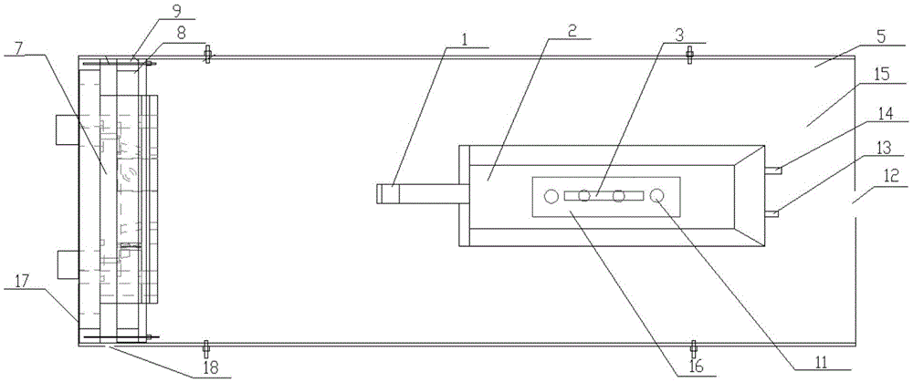
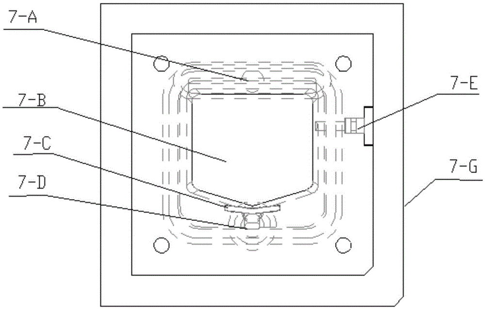
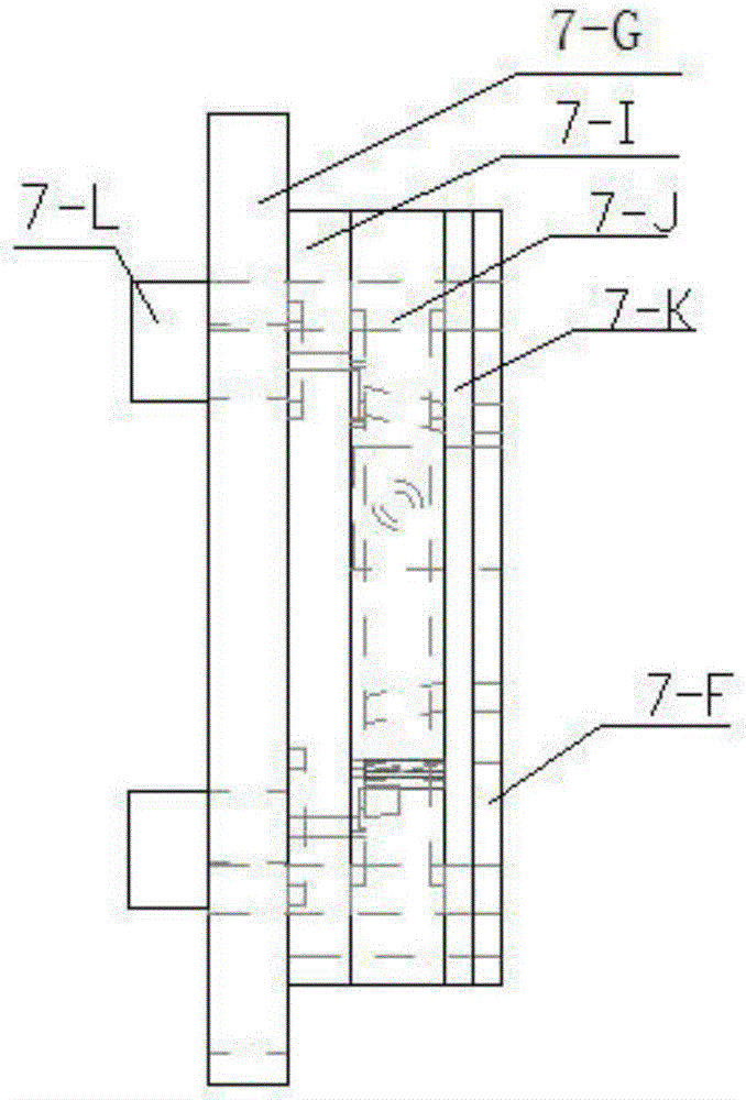
[0025] Optical lens 1, the specification is CCTVLENS, focal length 16mm, CCD camera 2, adopts Sony 700TVCCD model, the two are connected to form the core component of the microscopic shooting system, and are used to shoot the behavior changes of water fleas; the CCD camera is fixed on the sliding block 16 through M5 screws Above, the sliding block 16 is made of aluminum alloy, fixed in the sliding groove 3 by M4 screws, the sliding groove 3 is located on the bottom plate 15, the sliding block 16 can adjust the horizontal distance between the optical lens 1 and the reaction chamber 7 through the sliding groove 3, and the adjustment range 0-30mm. There are two nuts on the fixing screw M4, the bottom end of the screw M4 is fixed in the sliding groove 3 through these two nuts, the top of the screw M4 fixes the sliding block 16, and the position of the top of the screw is adjusted by changing the positions of the two nuts. Protruding distance, thereby adjusting the distance of the ...


PUM


Abstract

The invention discloses a closed microscopic shooting system which comprises a bottom plate and a shell arranged on the bottom plate. A sliding groove is fixed to the bottom plate. A lifting part capable of moving along the sliding groove in a reciprocating mode is arranged on the sliding groove. A CCD camera is fixed to the lifting end of the lifting part. A rectangular light source frame is arranged at one end of the shell. A reaction chamber is formed in the rectangular light source frame. The problem of contradiction between magnification times and the shooting view field area is solved; visible light imaging shooting is utilized for replacing an infrared light imaging mode, shooting speed is obviously increased, shooting clarity is obviously improved, and meanwhile the manufacturing cost is reduced greatly.

Description

technical field [0001] The invention relates to the field of water environment monitoring instruments and equipment, in particular to an airtight microscopic shooting system. It is suitable for real-time shooting of the kinematic behavior changes of daphnia, and is used to study the kinematic behavior characteristics, growth rate and life history characteristics of daphnia. This equipment is also suitable for the study of kinematic behavior characteristics, growth rate and life history characteristics of other micro-animals similar to daphnia. Background technique [0002] With the rapid development of social economy, my country's water environment problems are becoming more and more serious. At present, nearly 50% of the river sections and 90% of the urban waters in the country are polluted to varying degrees. Rivers in the north are polluted with water, while in the south there are frequent occurrences of no drinking water due to river pollution; the problem of groundwate...

Claims


Application Information

Patent Timeline
Patent Type & Authority Applications(China)
IPC IPC(8): G01N21/84G01N21/01
CPCG01N21/01G01N21/84
Inventor 王承法刘浩沈银武
Owner 武汉市天泉慧源环保科技有限公司
Learn More