
A light receiving component

A light-receiving component and component technology, applied in the field of optical communication, can solve problems such as increased difficulty, complicated packaging process, and inability to meet the miniaturization of modules

Active Publication Date: 2017-09-29
GUANGXUN SCI & TECH WUHAN
View PDF4 Cites 0 Cited by
  • Summary
  • Abstract
  • Description
  • Claims
  • Application Information

AI Technical Summary

Problems solved by technology

The advantage of this solution is that the OSA packaging process is relatively simple and the cost is low; the disadvantage is that 4 OSAs plus DEMUX need to take up a lot of space in the module, which cannot meet the requirements of increasingly smaller modules
The disadvantage is that this packaging process is more complicated and more difficult than the conventional OSA packaging process
In addition, because the price of the high-speed ceramic BOX shell is much higher than that of the conventional TO base and the conventional machined metal tube body, it is difficult to reduce the cost of the device

Method used


Image

  • A light receiving component
  • A light receiving component
  • A light receiving component

Examples


Embodiment Construction

[0034] The present invention will be further described in detail below with reference to the drawings and embodiments.

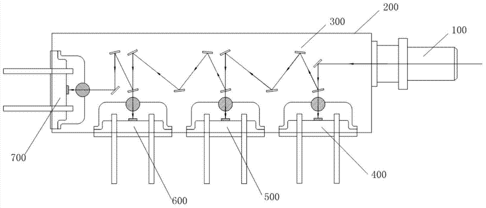
[0035] figure 1 It is a schematic structural diagram of an embodiment of a 4x10G / 4x25G optical receiving assembly provided by the present invention. Such as figure 1 As shown, a light receiving component according to the present invention includes a beam collimator 100 for shaping an external input beam into a collimated beam, and for splitting the collimated beam into multiple single-wavelength wave splitters Multiplexing filter set 300, detector TO component for receiving and detecting single-wavelength optical signals, and metal tube body 200 for encapsulating the light receiving component;

[0036] Wherein, one end of the beam collimator 100 is used to receive external input light, the other end of the beam collimator 100 is used to connect to the input port of the metal tube 200, and the wavelength division multiplexing filter The plate group 300 is distrib...


PUM


Abstract

The invention discloses a light receiving module, which comprises a beam collimator for shaping an external input beam into a collimating beam, a wavelength division demultiplexing filter set for decomposing the beam after being collimated into multiple single wavelengths, detector TO assemblies for receiving and detecting light signals of the single wavelengths and a metal tube body for packaging the light receiving module. The light receiving module of the invention is used for 4x10G / 4x25G and comprises the beam collimator, the metal tube body, the wavelength division demultiplexing filter set and the multiple detector TO assemblies. Directions and positions of incident beams are decomposed and adjusted through the wavelength division demultiplexing filter set, and the multiple detector TO assemblies and the metal tube body are packaged together to realize functions of 4x10G and 4x25G ROSA light devices. The light receiving module of the invention has the advantages of simple OSA packaging implementation process and low cost in the first scheme and device miniaturization packaging in the second scheme.

Description

Technical field [0001] The present invention relates to the field of optical communication technology, and in particular to an optical receiving component, which is mainly applied to a 4x10G / 4x25G optical communication system. Background technique [0002] With the continuous development of new high-bandwidth services and the increasing maturity of high-speed transmission technologies, application requirements based on 40G / 100G high-speed transmission are becoming more and more obvious. Compared with traditional 10G, 40G / 100G has obvious advantages: higher efficiency and higher bandwidth. . 40G / 100G optical modules mostly use multi-channel optical transceiver technology (4x10G, 4x25G), and transmit data at a rate of 10G or 25G per channel, and their capacity is 4 times that of traditional single-channel modules. Optical modules for 40G / 100G transmission generally require optical devices to meet the requirements of ensuring airtightness, and there are usually two schemes for meet...

Claims


Application Information

Patent Timeline
Patent Type & Authority Patents(China)
IPC IPC(8): G02B6/42G02B6/43
CPCG02B6/4286G02B6/43
Inventor 陈土泉宿志成宋旭宇
Owner GUANGXUN SCI & TECH WUHAN
Learn More