

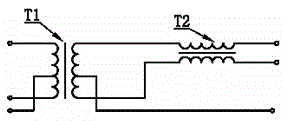
Network port transformer adopting electronic circuit structure to replace magnetic core coil
An electronic circuit structure and transformer technology, applied in multi-terminal pair network, frequency selection two-terminal pair network, etc., can solve the problems of a large number of manual winding coils, poor product competitiveness, high labor cost, etc., and achieve good controllability of product quality , high production efficiency and reduced labor costs
- Summary
- Abstract
- Description
- Claims
- Application Information
AI Technical Summary
Problems solved by technology
Method used
Image

Examples
Embodiment 1
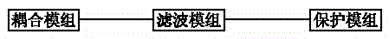
[0041] The present invention is a network interface transformer adopting an electronic circuit structure instead of a magnetic core coil, which includes a coupling module 1, a filtering module 2, and a protection module 3;
[0042] The coupling module is used for bidirectional coupling of high-speed network signals and isolation of DC signals;
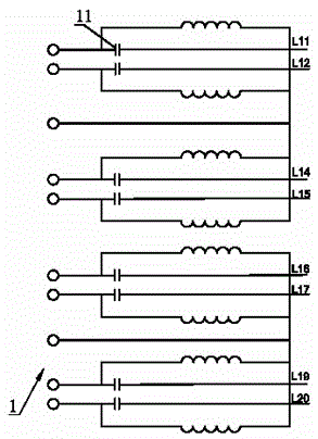
[0043] The coupling module adopts a capacitive coupling mode, and the coupling module is provided with four groups of capacitive coupling units, and each of the capacitive coupling units is provided with a group of capacitors 1;
[0044] The filtering module is used to filter high-frequency useless signals in network signals;
[0045] The filtering module 2 adopts a Bessel type stop-band filter;
[0046] The Bessel-type stopband filter includes an inductance element and a capacitor;
[0047] The protection module 3 is used to discharge abnormal high voltage and large current, and protect secondary electronic components and circuits; ...
Embodiment 2
[0053] The present invention is a network interface transformer adopting an electronic circuit structure instead of a magnetic core coil, which includes a coupling module 1, a filter module, and a protection module 3;
[0054] The coupling module is used for bidirectional coupling of high-speed network signals and isolation of DC signals;
[0055] The coupling module adopts a capacitive coupling mode, and the coupling module is provided with four groups of capacitive coupling units, and each of the capacitive coupling units is provided with a group of capacitors 1;
[0056] The filtering module is used to filter high-frequency useless signals in network signals;
[0057] The filtering module adopts a quasi-Bessel type TRACE filtering structure;
[0058] Described quasi-Bessel type TRACE filtering structure adopts the circuit structure on the PCB board to realize the function of Bessel type stop-band filter, and described quasi-Bessel type TRACE filtering structure is provided...
PUM
 Abstract
Description
Claims
Application Information