

Method and device for allocating and determining quasi-co-location
A configuration method and quasi-common technology, applied in the field of communication, can solve the problem of lack of cooperative UE large-scale feature parameter estimation and so on
- Summary
- Abstract
- Description
- Claims
- Application Information
AI Technical Summary
Problems solved by technology
Method used
Image

Examples
Embodiment 1
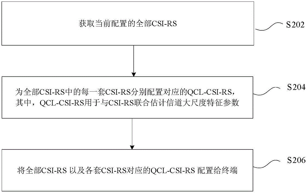
[0180] In order to enable the terminal to fully utilize the CSI-RS to effectively estimate the large-scale characteristic parameters of the channel, a method of configuring a QCL-CSI-RS for each set of CSI-RS is provided in this preferred embodiment. Based on this method, the network side device configures a corresponding QCL-CSI-RS for each set of configured CSI-RS, and configures related information of the QCL-CSI-RS to the terminal.
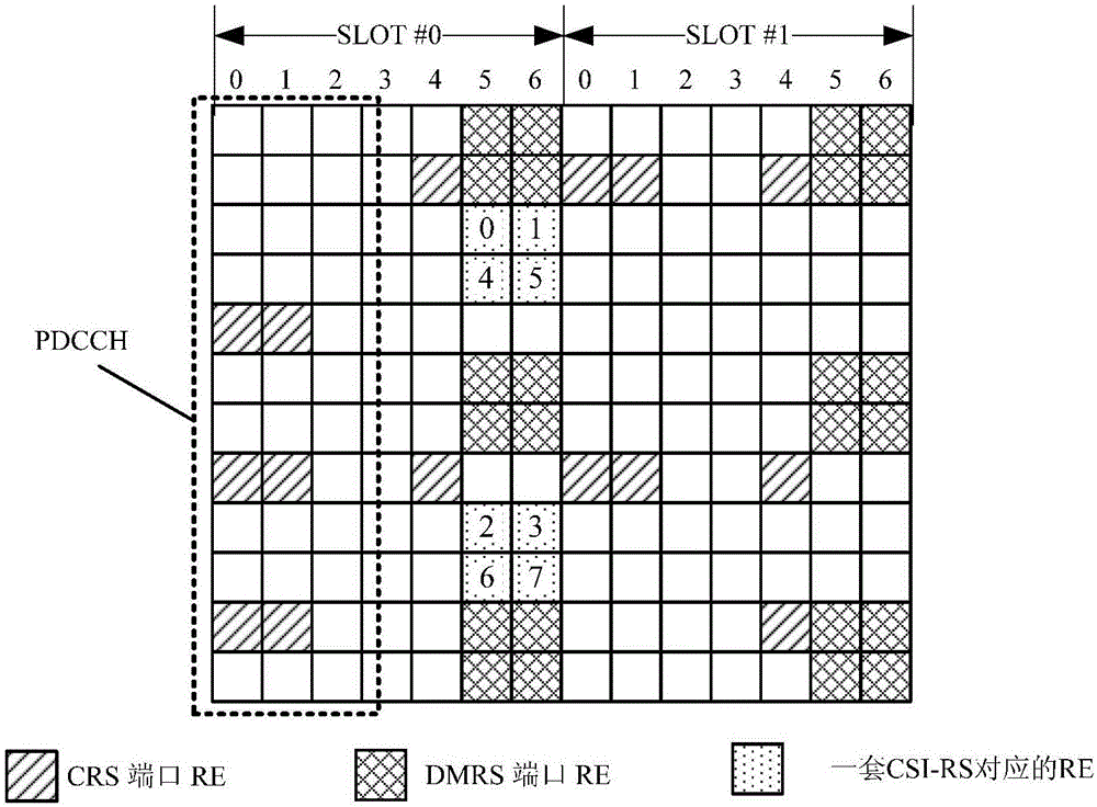
[0181] When the network side device configures QCL-CSI-RS for CSI-RS, in a preferred embodiment, it can refer to the CSI-RS usage of surrounding cells to determine the resource location, subframe / time slot of QCL-CSI-RS location and period information. For example: Figure 4 It is a schematic diagram of performing QCL-CSI-RS configuration according to a preferred embodiment of the present invention. Such as Figure 4 As shown, the resource location corresponding to the CSI-RS of the target cell is The illustrated REs, the CSI-RS configura...
Embodiment approach
[0185] In another preferred implementation manner, when configuring the QCL-CSI-RS, the network side device may also determine the relative positional relationship of the QCL-CSI-RS according to the speed of the terminal or the estimation of the potential frequency offset range. For example: when the mobile speed of the terminal is high and / or it is believed that there is a large frequency offset in the current transmission and reception, then when configuring the QCL-CSI-RS on the network side device, it should try to configure the QCL-CSI-RS to be the same as the CSI-RS. on subframes or similar subframes; when the mobile speed of the terminal is relatively low and / or it is believed that there is a small frequency offset in the current transmission and reception, the network side device should try to set the QCL-CSI-RS when configuring the QCL-CSI-RS - The RS is configured on a subframe different from the CSI-RS or on a subframe farther away;
[0186] Wherein, when the networ...
Embodiment 2
[0197] In the method of the above-mentioned preferred embodiment 1, the relevant QCL-CSI-RS parameters are notified to the terminal through configuration, and of course some parameters can also be configured in a pre-agreed manner between the network side device and the terminal.
[0198] In this preferred embodiment, in a preferred implementation manner, the network-side device and / or terminal defaults that the reference signal sequences corresponding to each port of the QCL-CSI-RS and the reference signal sequences corresponding to each port of the CSI-RS are based on the same scrambling Code ID is generated. Based on this method, when configuring the QCL-CSI-RS parameters for the terminal, the signaling overhead for configuring the QCL-CSI-RS reference signal sequence scrambling code ID can be saved.
[0199] In another preferred embodiment, the network-side device and the terminal can support only one port of the QCL-CSI-RS by default, and the port 0 of the CSI-RS by defau...
PUM
 Abstract
Description
Claims
Application Information