Cooling device and electronic device
A technology of heat dissipation device and circuit board, which is applied to the structural parts of electrical equipment, electrical components, cooling/ventilation/heating renovation, etc.
- Summary
- Abstract
- Description
- Claims
- Application Information
AI Technical Summary
Problems solved by technology
Method used
Image

Examples
Embodiment 1
[0018] In the prior art, electronic equipment is equipped with one or more heat-generating devices, and these devices will generate a large amount of heat during operation. If the heat is not dissipated in time, it may cause the electronic equipment to be stuck in operation, or even worse. It may cause the heat-generating device to burn out. Therefore, in order to dissipate the heat of the heating device in time, a radiator is arranged above the heating device, usually an air-cooled radiator, such as a cooling fan, a cooling fin, a combination of a cooling fan and a cooling fin, etc., but the cooling fan is rotating Noise will be generated when the fan is turned, the faster the rotation, the greater the noise, so if you want to achieve a better heat dissipation effect, you must increase the speed of the cooling fan, and at the same time, it will bring greater noise.
[0019] Then, in order to solve this problem, the present embodiment provides a heat dissipation device, which ...
Embodiment 2
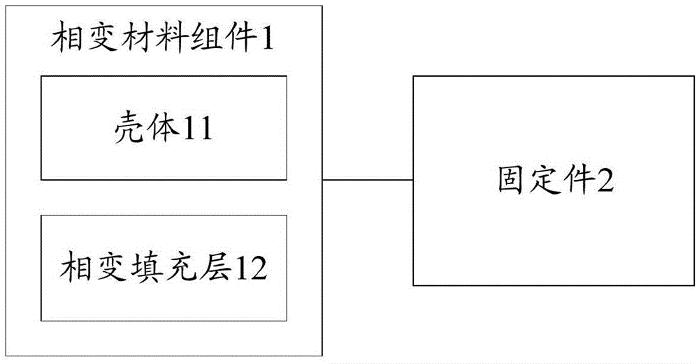
[0034] On the basis of Embodiment 1, this embodiment provides a heat dissipation device. The fixing part 2 is a metal base (Base), which is fixed on one side of the heating device, and the phase change material assembly 1 is arranged on the metal base.
[0035] Here, on one side of the heating device, the fixing member 2, that is, the metal base is fixed on the bearing member of the heating device by means of screwing, welding, riveting, bonding or clamping. For example, the heating device is arranged on the main board of the electronic equipment. At this time, the carrier of the heating device is the main board of the electronic equipment; body, the present invention is not specifically limited.
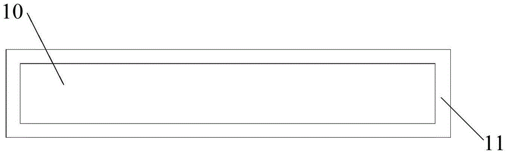
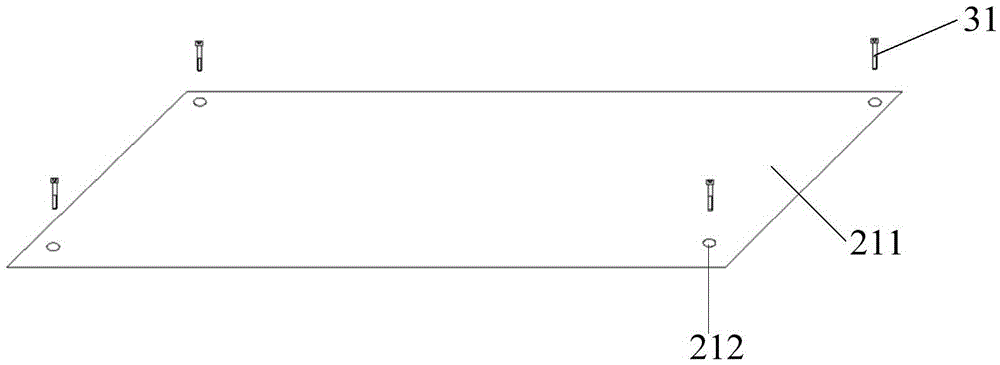
[0036] For example, see Figure 3A As shown, the metal base has at least one plane 211 parallel to the surface of the heating device. The phase change material assembly 1 is placed on the plane 211 and connected to the metal base. A plurality of screw holes 212 may be provided at t...
Embodiment 3
[0044] In the prior art, due to the improvement of the processing speed of the processor, its temperature rise rate is also accelerated, while the increase speed of the heat dissipation fan speed is relatively slow, so that the heat dissipation fan cannot increase the speed in time to match the temperature rise speed of the processor. The processor cannot dissipate heat in time, affecting work performance. Then, in order to solve this problem, when the processor is in an idle state, the speed of the cooling fan is set to a higher value. Then, when the processor starts to load, the cooling fan can keep up with the speed of the processor's temperature rise in time. In order to dissipate heat in time, however, since the processor does not need such a high speed to dissipate heat in the idle state, it causes a certain waste of resources, and at the same time makes the noise of the processor in the idle state higher. Therefore, there is a technical problem that the increase speed o...
PUM
 Abstract
Description
Claims
Application Information
 - R&D
- Intellectual Property
- Life Sciences
- Materials
- Tech Scout
- Unparalleled Data Quality
- Higher Quality Content
- 60% Fewer Hallucinations
Browse by: Latest US Patents, China's latest patents, Technical Efficacy Thesaurus, Application Domain, Technology Topic, Popular Technical Reports.
© 2025 PatSnap. All rights reserved.Legal|Privacy policy|Modern Slavery Act Transparency Statement|Sitemap|About US| Contact US: help@patsnap.com