Rapid carbon separation device for sewage treatment

A sewage treatment and carbon separation technology, applied in the field of water treatment, can solve the problems of high concentration of suspended solids in influent water, energy consumption, and reduced sewage treatment effect, so as to achieve the effect of reducing treatment cost and saving construction cost

Active Publication Date: 2016-04-13
WEIHAI FENGTAI NEW MATERIAL SCI & TECH
View PDF5 Cites 16 Cited by
  • Summary
  • Abstract
  • Description
  • Claims
  • Application Information

AI Technical Summary

Problems solved by technology

However, my country's sewage plants generally do not set up primary sedimentation tanks, generally only set up grilles, and some set up grit chambers, which will cause a high concentration of suspended solids in the front section of the biological tank, and some suspended solids will be deposited in the biological tank, which will not only increase The cost of maintenance and management of the biological pool is reduced, and the actual residence time of the sewage in the biological pool is reduced, which greatly reduces the treatment effect of the sewage
In addition, most of these suspended particles are organic matter, which consumes a lot of energy in the biological pool and increases the energy consumption of sewage treatment.
Although some sewage plant operators are aware of this serious problem, due to the limitation of the infrastructure area of ​​the sewage plant, it is impossible to set up a primary sedimentation tank with a large area to upgrade the sewage treatment plant.

Method used


Image

  • Rapid carbon separation device for sewage treatment
  • Rapid carbon separation device for sewage treatment
  • Rapid carbon separation device for sewage treatment

Examples


Embodiment 1

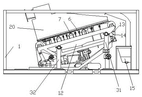
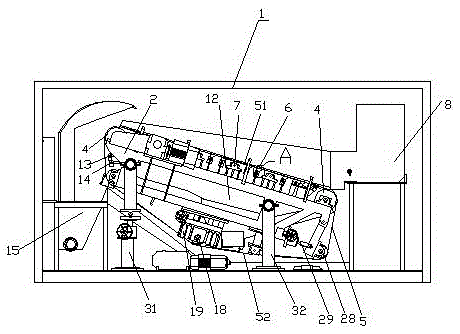
[0028] as attached figure 1 and attached image 3 As shown, the sewage treatment device provided in this embodiment includes a closed box body 1 , and a frame 2 is arranged inside the box body 1 , and the frame 2 is supported by a front support column 31 and a rear support column 32 .

[0029] as attached figure 1 and attached image 3 As shown, filter belt rolls 4 are respectively installed at both ends of the frame 2, wherein the filter belt roll 4 at one end is used as a drive shaft, and the filter belt roll at the other end is used as a driven shaft.

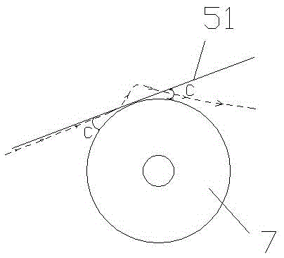
[0030] as attached Figure 5 As shown, an annular filter belt 5 is set on the filter belt roller 4 to form an upper filter belt 51 and a lower filter belt 52 .

[0031] as attached figure 1 and attached image 3 As shown, the top of the rear support column 32 is hinged with the frame 2, and the height of the front support column 31 is adjustable. By adjusting the height of the front support column 31, the entire frame ...

Embodiment 2

[0047] In the device provided in Example 1, there is a more prominent technical problem when using the sewage discharge box 8 to discharge sewage, which is that a large amount of sewage is deposited at the low end of the upper filter belt, and the large amount of sewage deposition causes the low end of the low end. As the pressure increases, the contact between the left and right vertical plates 16 and the upper filter belt 51 is difficult to effectively seal the sewage, resulting in a large amount of sewage overflowing from both sides of the lower end of the upper filter belt. In order to solve this technical problem, another sewage discharge device is provided in this embodiment.

[0048] as attached Figure 9 As shown, in the present embodiment, the sewage discharge box 8 and the left and right vertical plates 16 are removed, and the water distributor 20 is installed on the top of the upper filter belt 51 . The structure of water distributor 20 is attached Figure 10 As s...


PUM


Abstract

The invention relates to the technical field of water treatment and aims at providing a rapid carbon separation device for sewage treatment. The device comprises a filtration band which can load sewage at a minimum, a surge suction device is arranged below the filtration band, after the sewage is filtered through the filtration band, obtained clean water is collected below the filtration band, and impurities filtered out of the sewage are located on the filtration band and collected in a centralized mode. By means of application of the device to sewage treatment, the traditional sewage treatment process can be subverted thoroughly, construction cost of sewage treatment plants is greatly saved, and meanwhile sewage treatment cost is remarkably lowered.

Description

technical field [0001] The invention relates to the technical field of water treatment, in particular to a rapid carbon separation device for sewage treatment. Background technique [0002] The activated sludge sewage treatment method has developed rapidly in the past 100 years, and now more than 80% of sewage treatment plants use this method, which has made great contributions to human health and sustainable social development. Although the activated sludge sewage treatment method can effectively treat sewage, sewage treatment is a process of high energy consumption, and the electricity consumption accounts for about 1-3% of the total electricity consumption in our country. Moreover, with the improvement of sewage effluent quality standards , my country's sewage treatment plants upgrade is imminent. The concentration of suspended solids in general domestic sewage is 200-400ml / L, and in some areas it can reach about 600ml / L. This kind of sewage with high suspended particles...

Claims


Application Information

Patent Timeline
Patent Type & Authority Applications(China)
IPC IPC(8): B01D33/04B01D33/50B01D33/80
CPCB01D33/04B01D33/50B01D33/802B01D2201/081
Inventor 钱国峰刘海庆鲁海清吴舒拉王永波宋文进程明锟张源凯罗涛
Owner WEIHAI FENGTAI NEW MATERIAL SCI & TECH
Why Eureka
Try Eureka