Combined type vertical roller ring

A combined vertical roll technology, which is applied in the field of roll manufacturing, can solve the problems of low strength and non-abrasion resistance of the vertical roll ring, and achieve the effects of strong wear resistance, long service life and uniform force

Inactive Publication Date: 2016-04-13
SINOSTEEL XINGTAI MACHINERY & MILL ROLL
View PDF8 Cites 0 Cited by
  • Summary
  • Abstract
  • Description
  • Claims
  • Application Information

AI Technical Summary

Problems solved by technology

[0006] The technical problem to be solved in the present invention is to provide a combined vertical roller ring, which solves the problems of low strength and non-wear resistance of the vertical roller ring, and meets the rolling requirements

Method used


Image

  • Combined type vertical roller ring
  • Combined type vertical roller ring
  • Combined type vertical roller ring

Examples


Embodiment 1

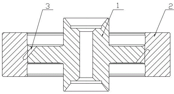
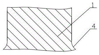
[0031] Such as figure 1 As shown, a combined vertical roller ring includes a ring sleeve 2 made of semi-steel and a shaft core 1 made of forged steel. The ring sleeve 2 and the shaft core 1 are fixedly connected by a connecting piece 3 composed of four evenly arranged positioning pins. , the angle between the joint surface of the ring sleeve 2 and the shaft core 1 and the positioning pin is 30°, among the four positioning pins, the positioning direction of two of them is 30° upward obliquely, and the positioning direction of the other two is 30° downward obliquely , the positioning pin is made of material with tensile strength ≥ 600Mpa and yield strength ≥ 360Mpa, such as 45# steel; figure 2 As shown, the edges and corners of the shaft core 1 are transitioned through the arc 4, and the radius R of the arc 4 is 5 mm.

[0032] After inspection, the safety factor of the vertical roller ring connected by the positioning pin is 5.0, which fully meets the requirements for use. Of...

Embodiment 2

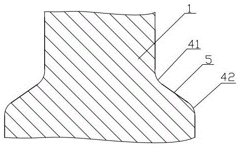
[0034] The difference between this embodiment and embodiment 1 is: see image 3 , the edge and corner of the shaft core 1 adopt the combination of arc 4 and oblique line 5, arc 4 includes arc ㄧ 41 and arc Ⅱ 42 separated from each other, and the radius R of arc ㄧ 41 and arc Ⅱ 42 Both are 5mm~20mm, they can be the same or different, for example, both can be 13mm, or they can be 12mm and 15mm respectively; the edge lines at the edges and corners are smoothly connected with arc ㄧ 41, and the arc ㄧ 41 is smoothly connected Oblique line 5, oblique line 5 is then smoothly connected to arc II 42, the angle between oblique line 5 and the horizontal line is 45-65°, for example, it can be 50°, 54°, 60°, so that the effective contact area is larger and the stress is smaller .

Embodiment 3

[0036] The difference between this embodiment and Embodiment 1 is: the angle between the joint surface of the ring sleeve 2 and the shaft core 1 and the positioning pin is 45°, the number of positioning pins is three, and the positioning direction of one of them is 45° upward obliquely, The positioning directions of the other two are obliquely downward at 45°.


PUM

PropertyMeasurementUnit
tensile strengthaaaaaaaaaa
yield strengthaaaaaaaaaa
shear strengthaaaaaaaaaa

Abstract

The invention relates to a combined type vertical roller ring applied to H-section steel and belongs to the technical field of manufacturing of a roller. The combined type vertical roller ring comprises a ring sleeve made from a semi-steel material and a central spindle made from a forged steel material, wherein the ring sleeve and the central spindle are fixedly connected by a connecting part; the safety coefficient of the vertical roller ring after connection is larger than or equal to 5.0; the connecting part is a positioning pin, a positioning key or an adhesive; the edge and corners of the central spindle are all in circular arc transition; the radius R of each circular arc is 5mm to 20mm; the circular arcs include a circular arc I and a circular arc II; an oblique line is smoothly connected between the circular arc I and the circular arc II; the included angle of the oblique line and the horizontal line is 45 to 65 degrees. The vertical roller ring disclosed by the invention is relatively high in strength, relatively high in wear resistance, small in stress after being connected, high in safety coefficient which is larger than or equal to 5.0, and capable of totally satisfying the rolling requirements.

Description

technical field [0001] The invention relates to a combined vertical roll ring, in particular to a vertical roll ring applied to H-shaped steel, and belongs to the technical field of roll manufacturing. Background technique [0002] The metallographic structure of semi-steel is generally composed of pearlite matrix and free carbides. This structural feature makes the performance of semi-steel rolls between cast steel and cast iron. The roll manufactured by it has little change in hardness from the surface to the core of the roll body, so it is especially suitable for the manufacture of section steel rolls with grooves on the roll body. [0003] The H-shaped steel vertical roll ring is a ring-shaped roll, which is used for rolling H-shaped steel. The H-shaped steel vertical roll ring currently used is a semi-steel vertical roll ring with an overall structure. During the use, the root of the shaft core hub has broken many times, seriously. Affect the efficiency of the rolling ...

Claims


Application Information

Patent Timeline
Patent Type & Authority Applications(China)
IPC IPC(8): B21B27/02
CPCB21B27/02B21B2203/18
Inventor 孙熙钊何彦杰王庆军
Owner SINOSTEEL XINGTAI MACHINERY & MILL ROLL
Why Eureka
Try Eureka