
Assembling fixture without corner bracket

A technology for assembling tooling and coding feet, which is applied in the field of assembling tooling without coding feet, can solve the problems of low probability of recycling, increase manufacturing processes, reduce production speed, etc., and achieve the effects of simple structure, improved production efficiency, and high versatility

Active Publication Date: 2016-04-13
GUANGZHOU SHIPYARD INTERNATIONAL LTD
View PDF6 Cites 10 Cited by
  • Summary
  • Abstract
  • Description
  • Claims
  • Application Information

AI Technical Summary

Problems solved by technology

[0002] Existing assembly operations such as butt jointing of steel plates and welding of steel plates and section steels all require temporary tooling to prevent displacement when the steel plates are butted, or when the steel plates are welded to the section steel. However, temporary tooling has the following defects: ( 1) There are many consumables for temporary tooling, the probability of recycling is small, and the versatility is poor, which increases the cost of materials; (2) When temporary tooling is erected, welding scars will be left on the surface of steel plates or section steel. It is necessary to disassemble and assemble the tooling separately and polish the weld scars on the surface of the steel plate and section steel, which increases the manufacturing process and reduces the production speed

Method used


Image

  • Assembling fixture without corner bracket
  • Assembling fixture without corner bracket
  • Assembling fixture without corner bracket

Examples


Embodiment Construction

[0013] The technical solutions of the present invention will be further described below in conjunction with the accompanying drawings and through specific implementation methods.

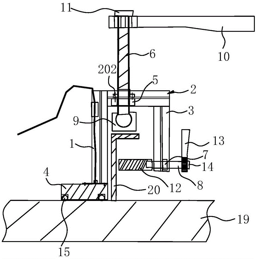
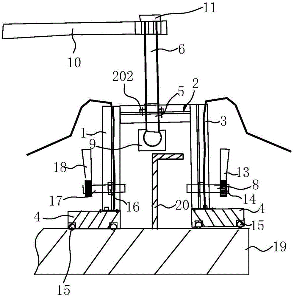
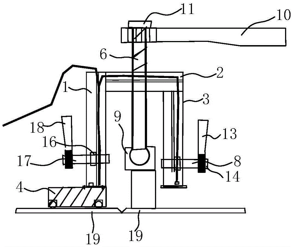
[0014] Such as Figures 1 to 3 As shown, in the embodiment of the present invention, the assembly tool without feet includes a first vertical support 1, a horizontal support 2 and a second vertical support 3, and the first vertical support 1 and the second vertical support 3 are vertically arranged on the horizontal support 2 respectively. The two ends are located on the same side of the horizontal bracket 2, the first vertical bracket 1 is provided with an electric sucker 4 at one end away from the horizontal bracket 2, the first screw sleeve 5 is arranged on the horizontal bracket 2, and the first screw sleeve 5 is threaded A first threaded mandrel 6 is screwed, and the first threaded mandrel 6 moves in the vertical direction, which includes a first pressing end and a first screwing end, a second ...


PUM


Abstract

The invention discloses an assembling fixture without a corner bracket. The assembling fixture without the corner bracket comprises a first vertical support, a transverse support and a second vertical support. The two vertical supports are perpendicularly arranged at the two ends of the transverse support respectively and located on the same side of the transverse support. An electric sucker is arranged at the end, away from the transverse support, of the first vertical support, a first screw rod sleeve seat is arranged on the transverse support, and a first screw rod is screwed on the first screw rod sleeve seat through a thread, moves in the vertical direction and comprises a first abutting end and a first screwing end. The second vertical support is provided with a second screw rod sleeve seat, a second screw rod is screwed on the second screw rod sleeve seat through a thread, moves in the horizontal direction and comprises a second abutting end and a second screwing end, and the first abutting end and the second abutting end are both located between the first vertical support and the second vertical support. Compared with the prior art, the assembling fixture without the corner bracket is simple in structure and high in universality, it can be avoided that craters are left on the surface of a steel plate or profile steel, the disassembling and polishing procedures in a later stage are omitted, the production efficiency is improved, and the manufacturing cost is reduced.

Description

technical field [0001] The invention relates to an assembly tool, in particular to an assembly tool without feet. Background technique [0002] Existing assembly operations such as butt jointing of steel plates and welding of steel plates and section steels all require temporary tooling to prevent displacement when the steel plates are butted, or when the steel plates are welded to the section steel. However, temporary tooling has the following defects: ( 1) There are many consumables for temporary tooling, the probability of recycling is small, and the versatility is poor, which increases the cost of materials; (2) When temporary tooling is erected, welding scars will be left on the surface of steel plates or section steel. It is necessary to separately disassemble and assemble the tooling and polish the welding scars on the surface of the steel plate and section steel, which increases the manufacturing process and reduces the production speed. Contents of the invention ...

Claims


Application Information

Patent Timeline
Patent Type & Authority Applications(China)
IPC IPC(8): B23K37/04
CPCB23K37/0443B23K2103/04
Inventor 唐合成宋玉成张兴国张沪生何志敏舒海威
Owner GUANGZHOU SHIPYARD INTERNATIONAL LTD
Learn More