Supercharge Your Innovation With Domain-Expert AI Agents!

Molds for Injection Molding of Carrier Reels

A tape carrier and injection molding technology, applied in the field of molds, can solve the problems of trapped air, waste of manpower, and the quality of tape carrier tape drop, and achieve the effects of uniform force, enhanced exhaust, and good exhaust effect.

Active Publication Date: 2018-02-02
SUZHOU DINGYOU PLASTIC PROD CO LTD
View PDF8 Cites 0 Cited by
  • Summary
  • Abstract
  • Description
  • Claims
  • Application Information

AI Technical Summary

Problems solved by technology

[0005] Especially for the injection molding process of the tape carrier, due to its light and thin structure, the gas can easily generate high pressure in the cavity. In the prior art, the invention patent with the application number "201520096313.1" discloses a tape carrier , which has the structure of positive disk surface, reverse disk surface and support shaft. The disk surface of this type of tape carrier is thinner, generally thinner than the disk surface of the optical disc, and this type of injection mold is generally equipped with a sprue in the center, and the melt When the material fills the cavity outward, the problem of trapped air is easy to occur, which will produce air bubbles, holes or depressions on the surface of the disk body, which will affect the quality of the tape carrier
[0006] In the prior art, the invention patent with the application number "201110223920.6" discloses a disc mold, which forms a gap for exhaust by setting a gap at the edge of the cavity of the injection molded part. The common means in most molds solves the problem of exhaust through this structure, but for molds using high-speed and high-pressure injection molding machines, the molten plastic is injected into the cavity at high pressure and high speed, so it is necessary to open Exhaust grooves with a large gap are used to solve the exhaust problem, but once the exhaust grooves are too large, there will be too thick burrs on the side of the molded injection molded part, and the burrs need to be further trimmed, which is a waste of manpower , resulting in a decrease in the quality of the tape carrier

Method used


Image

  • Molds for Injection Molding of Carrier Reels
  • Molds for Injection Molding of Carrier Reels
  • Molds for Injection Molding of Carrier Reels

Examples


Embodiment Construction

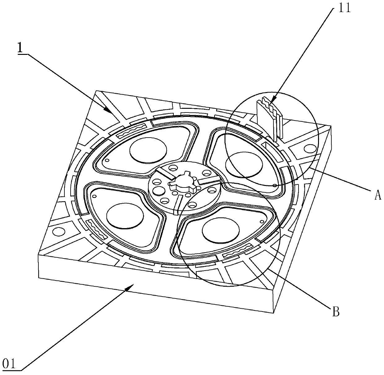
[0033] refer to Figure 1 to Figure 4 Embodiments of the present invention will be further described.

[0034] like figure 1As shown, a mold for injection molding of a tape carrier includes a mold base, and the mold base includes a core 01, a cavity 02 and a side core-pulling mechanism 03, between the core 01, the cavity 02 and the side core-pulling mechanism 03 A molding cavity 04 is formed, the core 01 is provided with a first exhaust structure 1 communicating with the upper end surface of the molding cavity 04, and the cavity 02 is provided with a second exhaust structure 2 communicating with the lower end surface of the molding cavity 04, Between the side core-pulling mechanism 03 and the core 01 and / or the cavity 02, a third exhaust structure 3 connected to the side of the molding cavity 04 is formed, and the tape carrier passes through the core 01, the cavity 02 and the side core-pulling Mechanism 03 is formed by setting the first exhaust structure 1, the second exhaus...


PUM


Abstract

The invention discloses a mould used for carrier band plate injection molding. According to the technical scheme, the key point is that the mould used for carrier band plate injection molding comprises a mould frame, wherein the mould frame comprises a mould core, a mould cavity and a side core-pulling mechanism; a forming cavity is formed among the mould core, the mould cavity and the side core-pulling mechanism; a first gas exhaust structure communicated with the upper end surface of the forming cavity is arranged in the mould core; a second gas exhaust structure communicated with the lower end surface of the forming cavity is arranged in the mould cavity; and a third gas exhaust structure communicated with the side surface of the forming cavity is formed between the side core-pulling mechanism and the mould core and / or the mould cavity. According to the mould, the first and the second gas exhaust structures are mutually matched with the forming cavity, and the first and the second gas exhaust structures are spatially vertical, so that flashing of the side surface of the carrier band plate is not increased, the gas is exhausted from different positions, and the size of the gas exhaust section at each position is reduced, and therefore, the mould has good surface forming effect, and effectively removes air trapping.

Description

technical field [0001] The invention relates to the field of moulds, and more specifically, it relates to a mold for injection molding of a carrier reel. Background technique [0002] The reel is a commonly used part, which is usually used to wind the belt, thus playing the role of fixing the belt, and there are guard plates on both sides, which can generally be called a part of the reel, such as the winding reel of the seat belt, Carrier reels for electronic parts, etc. [0003] In the prior art, some reels are made of high-hardness cardboard. In order to reduce the processing cost of the reels, due to the low cost of plastic materials, many reels are made of plastic injection molding, but for the tape carrier, Its quality is reflected in its lightness, thinness and high structural strength. Simply put, every time its size is reduced by one millimeter, in order to ensure its quality and performance, its processing difficulty rises linearly. Among these processing difficult...

Claims


Application Information

Patent Timeline
Patent Type & Authority Patents(China)
IPC IPC(8): B29C45/34
CPCB29C45/0025B29C45/34
Inventor 陈耀堂
Owner SUZHOU DINGYOU PLASTIC PROD CO LTD
Features
  • R&D
  • Intellectual Property
  • Life Sciences
  • Materials
  • Tech Scout
  • Unparalleled Data Quality
  • Higher Quality Content
  • 60% Fewer Hallucinations
Learn More