Wear-free hydraulic braking method, device and vehicle

A hydraulic braking, wear-free technology, applied in the direction of brake transmission, brakes, vehicle parts, etc., can solve the problems of increasing consumer extra expenses, easy to reduce the braking effect due to heat, easy to generate friction dust, etc. Simple and reliable, compact structure, the effect of increasing the safety factor

Inactive Publication Date: 2016-04-13
张学栋
View PDF9 Cites 4 Cited by
  • Summary
  • Abstract
  • Description
  • Claims
  • Application Information

AI Technical Summary

Problems solved by technology

[0003] It can be seen that the above-mentioned brake systems all rely on friction to brake. During the friction process, the kinetic energy of the hub is converted into heat energy and consumed. The heat generated not only easily reduces the braking effect, but even causes brake failure; it is also easy to generate friction dust, which becomes atmospheric Pollution sources that cannot be ignored in pollution
In addition, as the degree of wear and tear increases, the braking system needs to be replaced regularly to maintain its good braking performance and increase the additional expenditure of consumers.

Method used


Image

  • Wear-free hydraulic braking method, device and vehicle
  • Wear-free hydraulic braking method, device and vehicle
  • Wear-free hydraulic braking method, device and vehicle

Examples


Embodiment 1

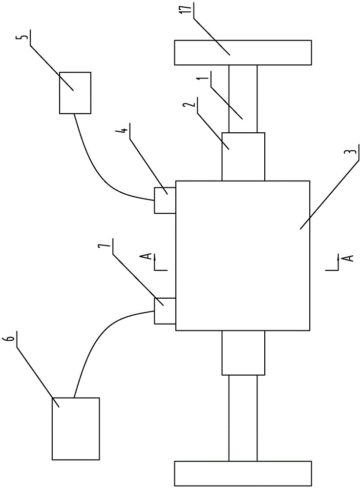
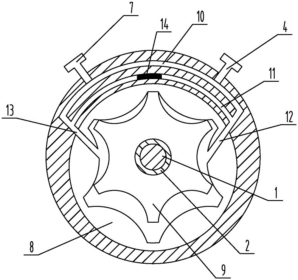
[0031] like figure 1 and figure 2 As shown, the present embodiment adopts the gear pump 3 of the internal meshing mode, and the pump housing of the gear pump 3 is provided with an inner ring gear 8, and the inner ring gear 8 is equipped with a gear 9, and the gear 9 is meshed with the inner ring gear 8, and the gear 9 rotates to drive the inner ring gear 8 to rotate, and the rotating shaft of the gear 9 is used as the pump shaft 2 of the gear pump 3 . A cavity is provided on the pump shaft 2 of the gear pump 3, the wheel shaft 1 of the vehicle is penetrated in the cavity, and the fixed connection between the wheel shaft 1 and the pump shaft 2 is realized through components such as keys or pins. Open the first channel 10 in the pump body of the gear pump 3, the first channel 10 communicates with the liquid inlet 13 and the liquid outlet 12 of the gear pump 3, the brake valve 4 is installed on the first channel 10, and the brake valve 4 is connected to the vehicle. The brake ...

Embodiment 2

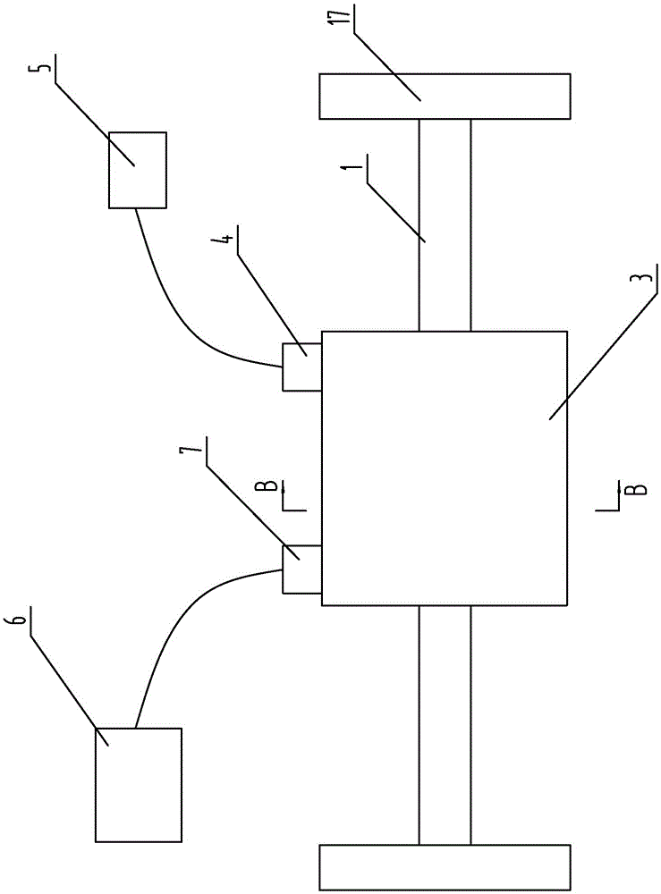
[0037] The difference between this implementation and the first embodiment is that: image 3 and Figure 4 As shown, the gear pump 3 of this embodiment adopts an external meshing mode, that is, a driving wheel 15 and a driven wheel 16 are arranged in the pump casing, the rotating shaft of the driving wheel 15 is used as the pump shaft 2, and the driven wheel 16 is only used to cooperate with the driving wheel 15 to complete the liquid. transmission, no connection with other devices.

[0038] In addition, the pump shaft 2 has two protruding sections protruding from the pump casing, the total length is compatible with the wheel shaft 1, and the hub 17 is assembled on the pump shaft 2, that is, the pump shaft 2 is used as the wheel shaft 1 to realize the combination of the pump shaft 2 and the wheel shaft 1. Two for one. This method is suitable for vehicles that have not left the factory, that is, the gear pump 3 with the appropriate length of the pump shaft 2 is directly selec...


PUM


Abstract

The invention discloses a wear-free hydraulic braking method, device and vehicle, and belongs to the technical field of vehicle braking. The braking device comprises a gear pump, wherein a liquid inlet and a liquid outlet are formed in the gear pump. The braking device is characterized in that a first passage through which the liquid inlet and the liquid outlet are communicated is also formed in the gear pump, and a braking valve is mounted on the first passage. According to the braking device, flow of liquid between the liquid inlet and the liquid outlet can be blocked by closing the first passage, and when a pump shaft of the gear pump rotates, pressure difference is formed between the liquid inlet and the liquid outlet, and the pressure difference compels the pump shaft to stop rotating to be reduced, so as to realize braking; the gear pump is a mature product for a long time, is stable in performance, and is simple and reliable in structure when used for realizing braking, so that hydraulic braking is realized, and friction braking in the prior art is innovated.

Description

technical field [0001] The invention belongs to the technical field of vehicle braking, and in particular relates to a wear-free hydraulic braking method, device and vehicle. Background technique [0002] With the development of the national economy, automobiles and other vehicles have gradually entered thousands of households and become the main means of travel or transportation for people. At present, the braking system on the vehicle is mainly disc or drum type. The disc brake is a brake that uses a stationary brake caliper to clamp the brake disc that rotates with the tire to generate friction and reduce the rotation speed of the wheel. Device; Drum brakes use hydraulic pressure to push the brake pads installed in the brake hub outward, so that the brake pads rub against the inner surface of the brake hub that rotates with the wheel to produce a braking effect. [0003] It can be seen that the above-mentioned brake systems all rely on friction to brake. During the frict...

Claims


Application Information

Patent Timeline
Patent Type & Authority Applications(China)
IPC IPC(8): B60T13/16
CPCB60T13/168
Inventor 张学栋高胜云
Owner 张学栋
Why Eureka
Try Eureka