Well logging device and logging method

A well logging and sub-carrier technology, which is applied in wellbore/well components, measurement, earthwork drilling and production, etc. It can solve the problems of long time consumption of well logging and slow down of well logging speed, etc.

Active Publication Date: 2019-02-19
GUANGXI UNIV
View PDF7 Cites 0 Cited by
  • Summary
  • Abstract
  • Description
  • Claims
  • Application Information

AI Technical Summary

Problems solved by technology

[0004] However, the above-mentioned processing method needs to stay at a certain point for 1000 cycles, resulting in a relatively long logging time, which in turn slows down the logging speed

Method used


Image

  • Well logging device and logging method
  • Well logging device and logging method
  • Well logging device and logging method

Examples


Embodiment Construction

[0027] The following will clearly and completely describe the technical solutions in the embodiments of the present invention with reference to the accompanying drawings in the embodiments of the present invention. Obviously, the described embodiments are only some, not all, embodiments of the present invention. Based on the embodiments of the present invention, all other embodiments obtained by persons of ordinary skill in the art without making creative efforts belong to the protection scope of the present invention.

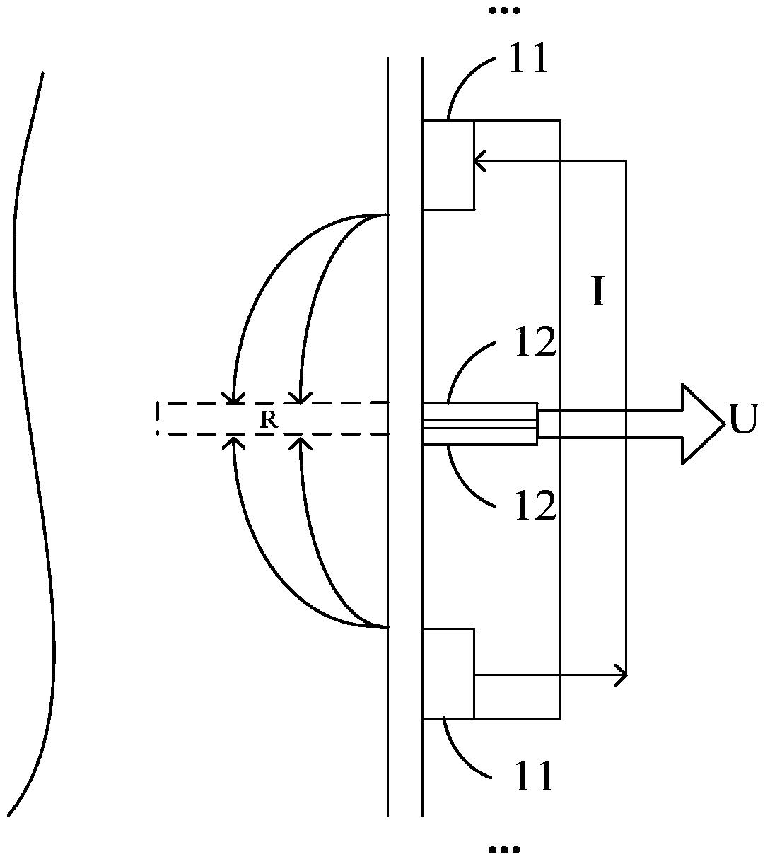
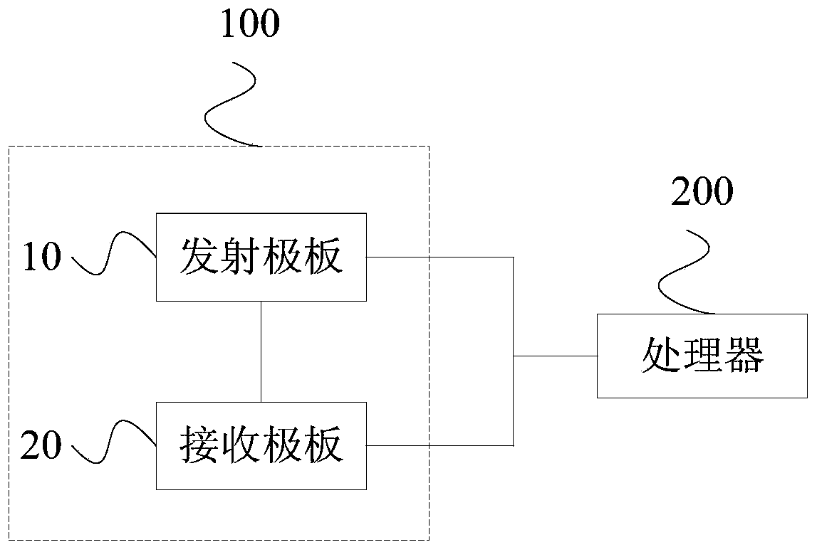
[0028] figure 2 A schematic structural diagram of the first embodiment of the logging device provided by the embodiment of the present invention; figure 2 As shown, the logging device provided in this embodiment includes: a pole plate 100 and a processor 200 electrically connected to the pole plate 100 ; wherein, each pole plate 100 includes: an emitter plate 10 and a receiver plate 20 .

[0029] In this embodiment, the emitter plate 10 is electrically conn...


PUM


Abstract

The invention provides a logging device and method. The device comprises pole plates and a processor. Each pole plate comprises a transmitting pole plate and a receiving pole plate, wherein the transmitting pole plate is electrically connected with the processor and the receiving pole plate, is used for generating at least two mutually-orthogonal preset subcarriers under the control of the processor, processes the mutually-orthogonal preset subcarriers, obtains transmitting signals and is triggered to transmit the transmitting signals to the receiving pole plate; the processor is electrically connected with the receiving pole plates and used for receiving receiving signals of the receiving pole plates, processing the receiving signals, obtaining amplitude values corresponding to the mutually-orthogonal preset subcarriers and obtaining corresponding resistances according to the amplitude values corresponding to the mutually-orthogonal preset subcarriers; then, the resistances are sent to a ground server so as to allow the ground server to obtain data of a borehole stratum according to each resistance, the logging time is shortened, and the logging efficiency is improved.

Description

technical field [0001] The invention relates to the technical field of formation resistivity logging, in particular to a logging device and a logging method. Background technique [0002] In the process of oil exploration, it is often necessary to measure the rock formation around the well wall to obtain formation data. At present, the logging method mainly adopts the electrical logging method, which mainly uses low-frequency electromagnetic waves to transmit in the underground rock formations. Through Ohm's law, the resistivity data of the rock formations around the well wall can be obtained, and the resistivity data can be obtained. Whether the fluid in the formation is oil with high resistivity or water with low resistivity. specific, figure 1 It is a schematic diagram of the basic principle of the electrical logging system in the prior art, such as figure 1 As shown, the electrical logging system mainly includes a plurality of emitter plates 11, a plurality of receive...

Claims


Application Information

Patent Timeline
Patent Type & Authority Patents(China)
IPC IPC(8): E21B49/00E21B47/12
CPCE21B47/12E21B49/00
Inventor 蔡毓杨锋沙爽
Owner GUANGXI UNIV
Why Eureka
Try Eureka