Comprehensive tunnel drainage, precipitation and pressure reduction construction method

A construction method and tunnel technology, which is applied in drainage, earthwork drilling, safety devices, etc., can solve the problems of disrupting the balance of water resources system, abandoning and relocating tunnels, and engineering disasters, so as to improve the physical and mechanical performance indicators of the formation and ensure safety , The effect of protecting the quality and safety of the project

Active Publication Date: 2016-04-13
CHINA RAILWAY 19TH BUREAU GRP SECOND ENG CO LTD
View PDF12 Cites 4 Cited by
  • Summary
  • Abstract
  • Description
  • Claims
  • Application Information

AI Technical Summary

Problems solved by technology

[0005] (1) Causing engineering disasters and casualties
Tertiary sand-mudstone areas are characterized by rich water and mud and sand. When a large water inrush occurs during the construction of a tunnel, it is often accompanied by mud and sand gushing, which will submerge the tunnel and destroy the equipment. Tunnels are abandoned and easy to locate, and even cause heavy casualties. For example, tunnels on the Yiwan Railway Red Deer and other tunnels are constructed on a flat surface, and the surrounding rocks in the fracturing arch of the dissolved cavity water body are overlying, causing extremely large water inrush disasters. The maximum water inrush is as high as 30 ×104m3 / h, causing 11 deaths
[0007] (3) Destroying the balance of the water resource system
[0008] (4) Other potential hazards

Method used


Image

  • Comprehensive tunnel drainage, precipitation and pressure reduction construction method

Examples


Embodiment Construction

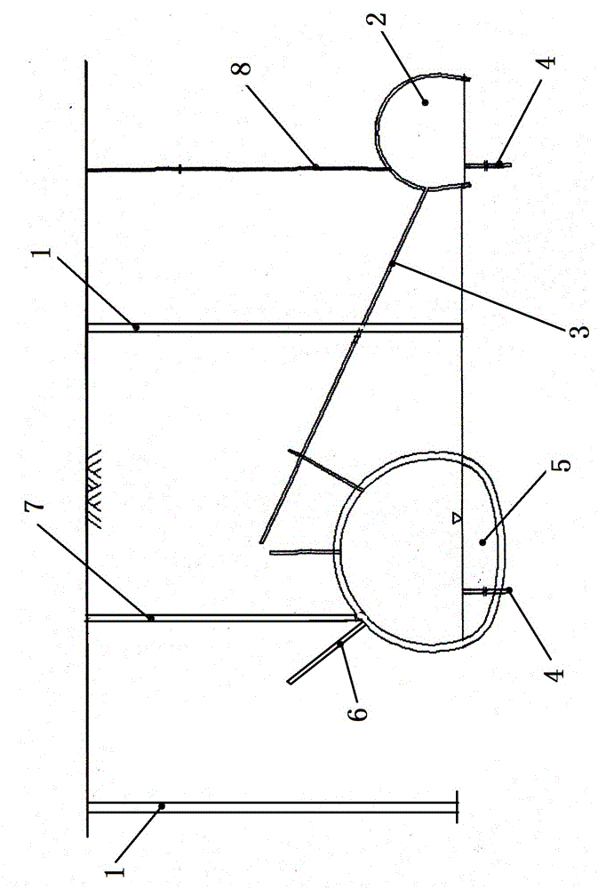
[0020] Refer to attached figure 1 , the ground surface precipitation well 1 is respectively drilled at the place of 8 meters away from the sidelines on both sides of the positive hole 5 on the surface, and the level pilot hole 2 is set near the positive hole on the surface, so as to increase the excavation face while reaching the drainage and dewatering decompression, by Drainage holes 3 are drilled in the flat pilot tunnel towards the surface towards the obliquely upward direction of the main tunnel, tunnel base dewatering wells 4 are drilled at the base of the surface towards the normal tunnel and the base of the flat pilot tunnel, and several slopes are drilled on the surface towards the vault of the main tunnel obliquely forward and upward. To the drain hole 6, the ground surface is set up the vertical drain hole 7 of the positive hole above the vault of the positive hole, and the vertical drain hole 8 of the flat pilot hole is also punched above the vault of the flat pilot...


PUM


Abstract

The invention provides a comprehensive tunnel drainage, precipitation and pressure reduction construction method, relates to an in-tunnel drainage, ground precipitation and comprehensive pressure reduction construction method for a water and mud burst segment of a tertiary system sand shale tunnel and is mainly designed to solve the problems that an existing tunnel is prone to deformation, collapse and even water burst and mud burst in the tertiary system sand shale construction process. Ground precipitation wells are drilled at the positions, eight meters away from the side lines on the two sides, of a ground-direction positive hole, a flat guide hole is formed near the ground-direction positive hole, a drainage hole is formed in the inclined upper direction of the ground-direction positive hole relative to the flat guide hole, tunnel substrate precipitation wells are drilled in both the substrate of the ground-direction positive hole and the substrate of the flat guide hole, a plurality of inclined drainage holes are formed above the inclined front portion of a vault of the ground-direction positive hole, a positive hole vertical drainage hole is formed above the vault of the ground-direction positive hole, and a flat guide hole vertical drainage hole is further formed above the vault of the flat guide hole. The comprehensive tunnel drainage, precipitation and pressure reduction construction method has the advantages that geological disasters such as collapse, deformation, water burst and mud burst are avoided, and tunnel construction safety can be guaranteed.

Description

Technical field: [0001] The invention relates to a construction method of water discharge, surface precipitation and comprehensive decompression in the water gushing and mud gushing section of the tertiary sand mudstone tunnel. Background technique: [0002] With the construction of large-scale, modernized and high-standard urban roads and transportation projects in my country, the number and construction scale of tunnel projects continue to expand, and the geological conditions passed through are becoming more and more complex. Tertiary sand-mudstone is a complex geological surrounding rock. The characteristics of Tertiary sand-mudstone: the main component is clay minerals, containing a small amount of silt, of which the silt content is 25%-50%, the clay content is 75%-50%, and it is easy to soften and erode when exposed to water; the surrounding rock Poor self-stabilization ability, broken, swollen, low strength; development of joints and fissures, etc. The above characte...

Claims


Application Information

Patent Timeline
Patent Type & Authority Applications(China)
IPC IPC(8): E21F16/02
CPCE21F16/02
Inventor 杨保旭李红阳张明双李红峰邢晓锋李德武马学宁
Owner CHINA RAILWAY 19TH BUREAU GRP SECOND ENG CO LTD
Why Eureka
Try Eureka