Electric switching valve

A technology of electric switching and valve seat, applied in the direction of sliding valve, valve details, valve device, etc., can solve the problem of unable to meet the requirements of the refrigeration system, and achieve the effect of reducing energy consumption, improving adjustment accuracy and reducing energy loss

Inactive Publication Date: 2016-04-13
ZHEJIANG SANHUA INTELLIGENT CONTROLS CO LTD
View PDF9 Cites 27 Cited by
  • Summary
  • Abstract
  • Description
  • Claims
  • Application Information

AI Technical Summary

Problems solved by technology

[0007] However, with the optimization and improvement of the refrigeration system, it is necessary to be able to control the refrigerant flow more accurately and reduce energy loss. The above-mentioned electric switching valve can only realize the opening and closing function of the outlet, which cannot meet the further requirements of the refrigeration system.

Method used


Image

  • Electric switching valve
  • Electric switching valve
  • Electric switching valve

Examples


Embodiment Construction

[0039] The core of the present invention is to provide an electric switching valve, which can adjust the refrigerant flow rate and reduce energy loss, thereby reducing the energy consumption of the refrigeration system.

[0040] In order to enable those skilled in the art to better understand the solution of the present invention, the present invention will be further described in detail below in conjunction with the accompanying drawings and specific embodiments.

[0041] Please refer to Figure 4 , Figure 4 It is a structural schematic diagram of a specific embodiment of the electric switching valve provided by the present invention.

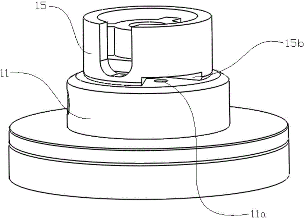
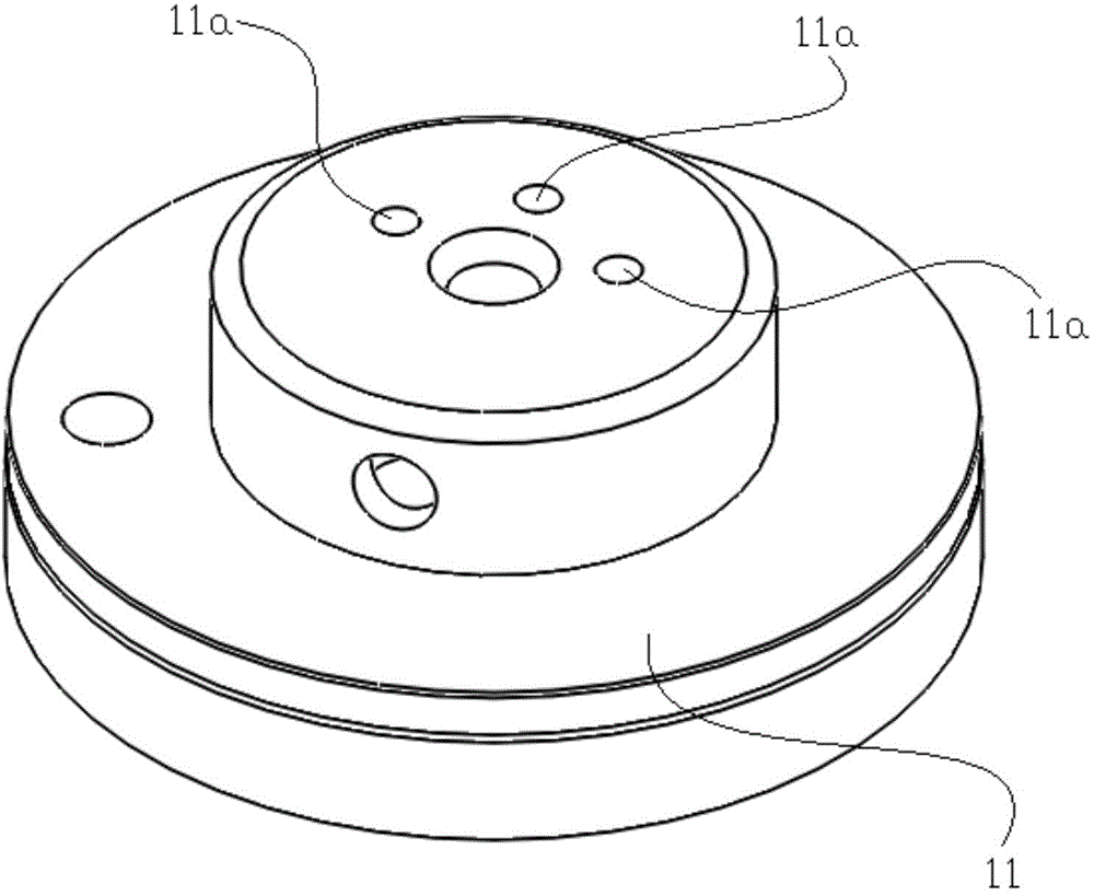
[0042] As shown in the figure, the electric switching valve includes a valve seat 21 and a housing 22 fixed with the valve seat 21 to form a sealed valve chamber.

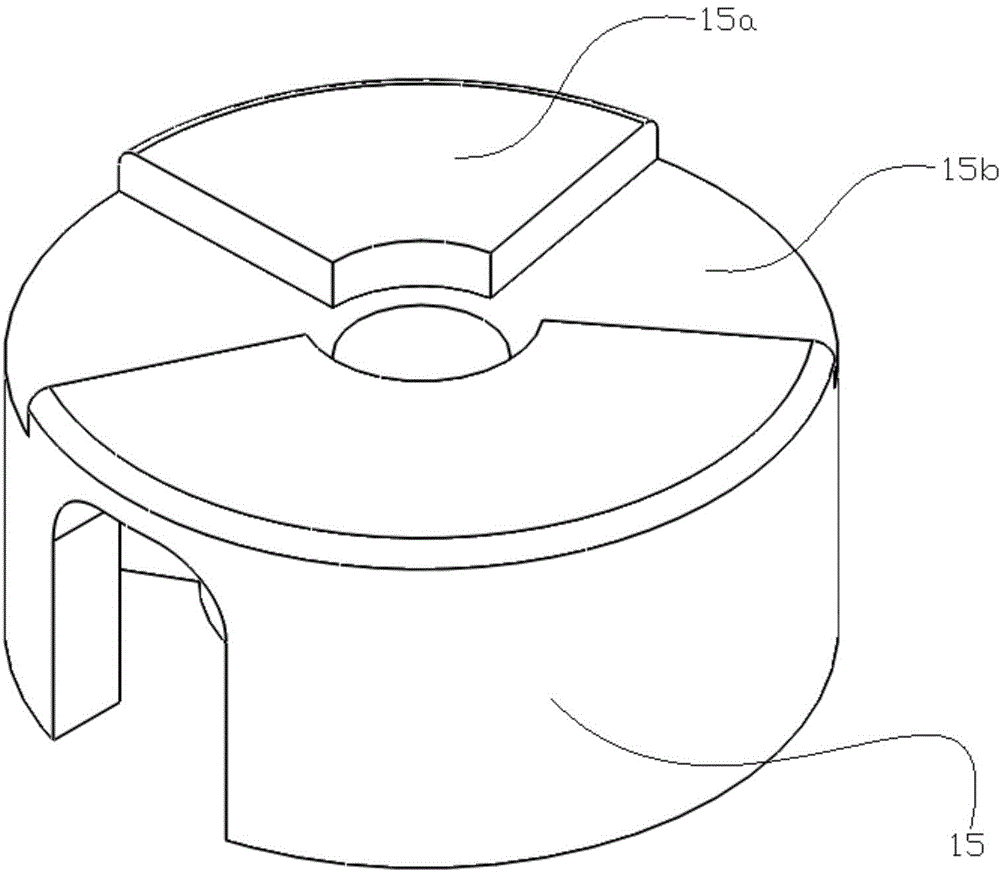
[0043] Wherein, the upper end surface of the valve seat 21 has an outlet, and a slider 25 sealingly attached to the upper end of the valve seat 21 is also provided in the valve ...


PUM


Abstract

The invention discloses an electric switching valve. The electric switching valve comprises a valve seat and a sliding block which is attached to the upper end of the valve seat in a sealing mode. The sliding block can rotate relative to the valve seat so as to open and close a guiding-out opening of the valve seat. The number of the guiding-out opening is one. A through hole is formed in the sliding block. The flow area of the through hole is smaller than that of the guiding-out opening. In the rotating process of the sliding block, the through hole can be communicated with the guiding-out opening. According to the electric switching valve, the refrigerant flow can be controlled, the energy loss is reduced, and energy consumption of a refrigerating system is reduced.

Description

technical field [0001] The invention relates to the technical field of refrigeration, in particular to an electric switching valve. Background technique [0002] In refrigeration cycle devices, such as refrigerators, electric switching valves are usually used as control components to change the refrigerant flow path. [0003] The existing electric switching valve includes a valve seat and a casing fixed above the valve seat, and also includes a motor, the coil part of the motor is outside the casing, and the rotor part is built in the casing. [0004] A valve cavity is formed inside the shell, and the valve seat is provided with an inlet channel and an outlet channel, and its upper end surface has an outlet port corresponding to the outlet channel, and a slider is also arranged on the valve seat to seal and fit with the upper end surface, and the slider is on the rotor part. It rotates synchronously under the drive and cooperates with the export port to control the opening ...

Claims


Application Information

Patent Timeline
Patent Type & Authority Applications(China)
IPC IPC(8): F16K31/02F16K3/30
Inventor 不公告发明人
Owner ZHEJIANG SANHUA INTELLIGENT CONTROLS CO LTD
Why Eureka
Try Eureka