Micro-channel heat exchanger and mounting method

A micro-channel heat exchanger, an integrated technology, applied in the direction of heat exchanger shell, heat exchange equipment, evaporator/condenser, etc., can solve the problem of easy deformation of baffle groove, increase of product leakage, and deterioration of header strength and other problems, to achieve the effect of high connection strength, avoid leakage, and facilitate assembly

Active Publication Date: 2016-04-13
ZHEJIANG DUNAN ARTIFICIAL ENVIRONMENT
View PDF6 Cites 10 Cited by
  • Summary
  • Abstract
  • Description
  • Claims
  • Application Information

AI Technical Summary

Problems solved by technology

But when the length of the header is long, after the partition is installed, it is difficult for the distribution pipe to align with the hole of the partition and pass through the partition. At the same time, when the header is required to separate multiple areas, it will require many Baffles, that is to say, there are many partition slots on the collector, so many welding points will be added to the collector, which increases the chance of product leakage. At the same time, the collector is cut with many partition slots. , the strength of the header becomes worse, and the partition groove is easily deformed, which increases the difficulty of assembly

Method used


Image

  • Micro-channel heat exchanger and mounting method
  • Micro-channel heat exchanger and mounting method
  • Micro-channel heat exchanger and mounting method

Examples


Embodiment Construction

[0029] The following combination Figure 1 to Figure 5 Embodiment 1 of the present invention will be specifically described.

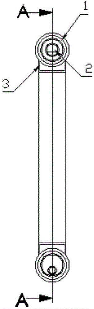
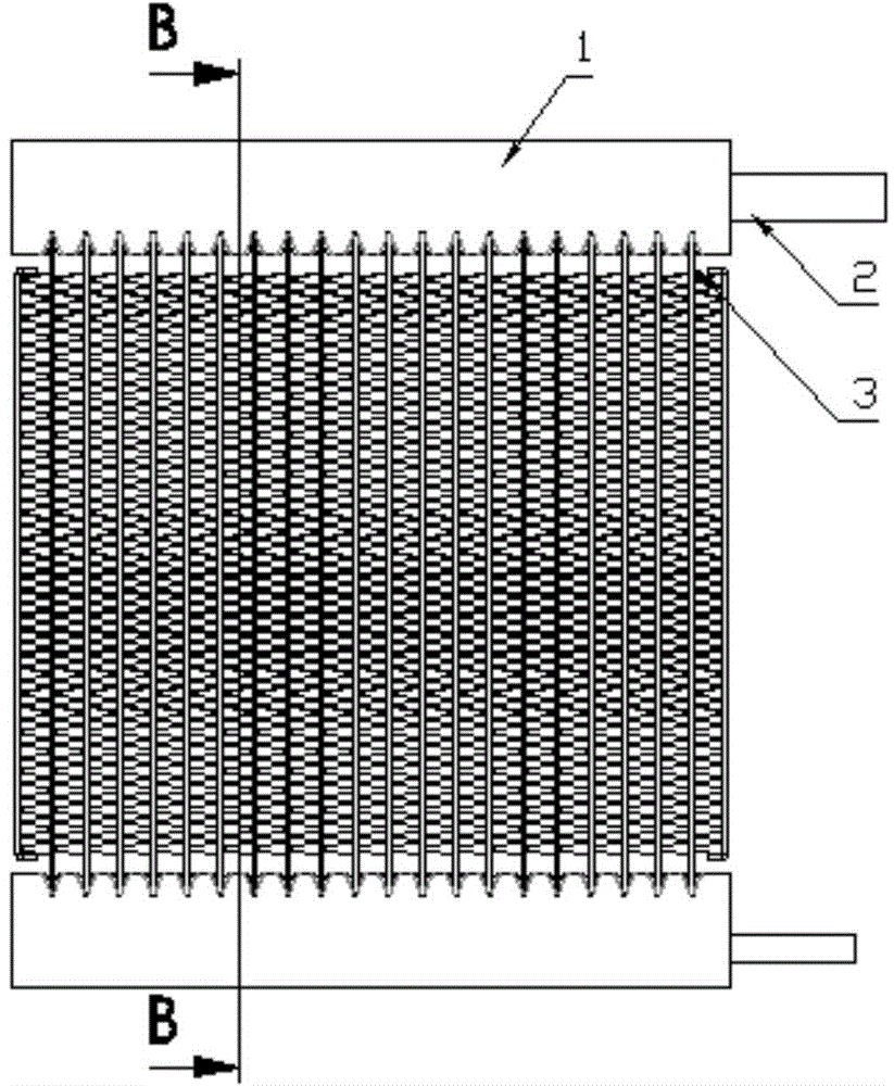
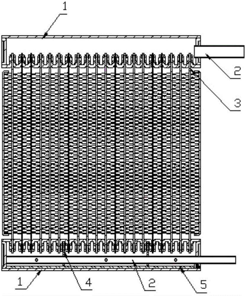
[0030] A microchannel heat exchanger, comprising a header 1 and a distribution pipe 2 arranged in the header 1, the distribution pipe 2 is provided with several distribution holes 21 along the axial direction, and the ends of the flat tubes 3 are inserted side by side In the collecting pipe 1, the distribution pipe 2 is integrally fixed with several partitions 4 along the axial direction, the distribution pipe 2 is movably inserted into the collecting pipe 1, and the distribution pipe 2 is also inserted into the collecting pipe 1 The fixed closure 5, the partition plate 4 cooperates with the closure 5 and the inner wall of the header 1 to separate several independent liquid separation areas inside the header 1.

[0031] The present invention still uses the separator 4 to separate several independent liquid separation areas inside the header 1, so as t...


PUM


Abstract

The invention discloses a micro-channel heat exchanger and a mounting method. The micro-channel heat exchanger comprises collecting pipes and distributing pipes arranged in the collecting pipes, wherein the distributing pipes are provided with a plurality of distributing holes in the axial direction, and the end parts of flat pipes are inserted into the collecting pipes side by side; a plurality of baffles are integrally fixed on the distributing pipes in the axial direction, and the distributing pipes are movably inserted into the collecting pipes; sealing members for fixing the distributing pipes are also inserted into the collecting pipes, and the baffles, the sealing members and the inner walls of the collecting pipes are matched in the collecting pipes, so that a plurality of independent liquid distributing regions are formed. According to the mounting method disclosed by the invention, the baffles and the distributing pipes are integrally fixed, and then are movably inserted into the collecting pipes, so that the collecting pipes can keep integral structures, and defects caused by the condition that plate grooves are cut in a conventional structure are overcome; therefore, the intensity of the collecting pipes is guaranteed, and the leakage is avoided.

Description

technical field [0001] The invention relates to heat exchanger technology, in particular to a microchannel heat exchanger. Background technique [0002] When the microchannel heat exchanger is used as an evaporator, since two-phase refrigerant enters, it is easy to cause uneven liquid separation and affect the heat exchange effect. At present, the commonly used liquid separation technology is: insert a liquid separation pipe from the end of the header There are holes in the liquid distribution pipe, but the refrigerant will be redistributed once it flows into the header after being sprayed out from the small hole of the distribution pipe. Since the tube lengths of each flat pipe are different, even if the refrigerant sprayed from the distribution pipe is relatively uniform, The refrigerant flowing into the flat tube for heat exchange will also cause uneven liquid distribution due to the secondary distribution of the header. [0003] In order to solve this problem, the usual...

Claims


Application Information

Patent Timeline
Patent Type & Authority Applications(China)
IPC IPC(8): F25B39/04F28F9/22F28F9/013
Inventor 钟建法汪峰
Owner ZHEJIANG DUNAN ARTIFICIAL ENVIRONMENT
Why Eureka
Try Eureka