
Doppler ultrasonic flowmeter

An ultrasonic and flowmeter technology, applied in the direction of measuring flow/mass flow, liquid/fluid solid measurement, measuring devices, etc., can solve problems such as stagnation of production work, errors in measurement results, inconvenient installation and maintenance of instruments, etc., to achieve easy Effects of setting, increasing precision and stability, speeding up data processing

Inactive Publication Date: 2016-04-13
牛誉博
View PDF1 Cites 4 Cited by
  • Summary
  • Abstract
  • Description
  • Claims
  • Application Information

AI Technical Summary

Problems solved by technology

At present, the existing flowmeter needs to be placed in the fluid when measuring the fluid flow, and the measuring element needs to be installed in the fluid, which will lead to the state of fluid flow, and generate additional resistance, and the obtained measurement results will have errors; The installation and maintenance of the instrument are inconvenient, which will lead to the stagnation of production work on the spot; for example, the reference patent number is 200580006192.6, which discloses a Doppler ultrasonic flowmeter, which has: an ultrasonic sending mechanism; a flow velocity distribution measuring mechanism and the flow rate measurement mechanism, wherein the velocity distribution measurement mechanism has a calculation mechanism for calculating the flow velocity distribution of the measured fluid; the calculation mechanism has: a calculation unit for calculating the flow velocity distribution of the measured fluid in the fluid piping, for A central position detection unit for obtaining the central position of the fluid piping, and a selection unit for selecting an area in the fluid piping used for calculating the flow velocity distribution in units of divided areas divided by the central position; the flow velocity distribution measuring means is configured as follows: When calculating the flow velocity distribution, one of the divided areas selected by the selection unit is used for calculation, and the flow velocity distribution of the measured fluid in the measurement area is measured assuming that the flow velocity distribution is symmetrical with respect to the central position.

Method used


Image

  • Doppler ultrasonic flowmeter
  • Doppler ultrasonic flowmeter

Examples


Embodiment Construction

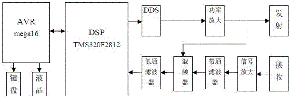
[0015] Such as figure 1 Shown is a hardware block diagram of a Doppler ultrasonic flowmeter system of the present invention. The figure includes a transmitting module, a receiving sampling module, and a processing and control module; the transmitting module includes a DDS circuit, a power amplifier circuit and an ultrasonic transducer, which are connected in sequence; the receiving sampling module includes a signal amplifier circuit, and a belt connected to the amplifier circuit. The pass filter, the mixer connected with the low-pass filter, the low-pass filter connected with the mixer, and the power amplifier circuit is connected with the mixer; the processing and control module is set with DSP chip as the core, including The AVR in which the DSP chips communicate with each other is also provided with a keyboard module and a liquid crystal display module outside the AVR.

[0016] The DDS circuit provided in the transmitting module of the present invention is used to generate...


PUM


Abstract

Provided is a doppler ultrasonic flowmeter. The doppler ultrasonic flowmeter has following beneficial effects: the doppler ultrasonic flowmeter is high in response speed of velocity fluctuation and not sensitive to factors such as pressure, viscosity, temperature, density and conductivity of fluid; and zero drift is avoided. The doppler ultrasonic flowmeter comprises an emission module, a reception and sampling module and a processing and control module. The key of the structure is characterized in that the emission module comprises a DDS circuit, a power amplification circuit and an ultrasonic transducer, all of which are sequentially connected; the reception and sampling module comprises a signal amplification circuit, a band pass filter connected with the amplification circuit, a frequency mixer connected with the low pass filter and a low pass filter connected with the frequency mixer; the power amplification circuit is connected with the frequency mixer; and the processing and control module is provided with a DSP core as a core and comprises an AVR in communication with the DSP core; and the outside of the AVR is further provided with a key module and a liquid crystal display module.

Description

technical field [0001] The invention is applied in the technical field of flow measurement, and in particular relates to a Doppler ultrasonic flowmeter. Background technique [0002] Flow measurement is very important in industrial production, energy saving, environmental monitoring and protection, scientific experiments and process control. [0003] With the development of industrial production and scientific research, flow measurement technology has developed very rapidly, and new flow measurement instruments are constantly emerging. When the ultrasonic wave propagates in the flowing fluid, it carries the information of the fluid velocity. Therefore, the flow velocity of the fluid can be detected by the received ultrasonic waves, and then converted into a flow rate. This is the measurement principle of the ultrasonic flowmeter. At present, the existing flowmeter needs to be placed in the fluid when measuring the fluid flow, and the measuring element needs to be installed...

Claims


Application Information

Patent Timeline
Patent Type & Authority Applications(China)
IPC IPC(8): G01F1/66
Inventor 牛誉博汪邵严
Owner 牛誉博
Learn More