Eureka AIR delivers breakthrough ideas for toughest innovation challenges, trusted by R&D personnel around the world.

Strong current short-circuit testing transformer with air gaps and implementation method therefor

A technology of short-circuit test and implementation method, which is applied in the field of transformer manufacturing, can solve problems such as failure to meet standard requirements, affect test voltage, and current waveform output, and achieve the effect of reducing magnetic saturation of iron core and reducing residual magnetism

Active Publication Date: 2016-04-13
TBEA SHENYANG TRANSFORMER GRP CO LTD
View PDF6 Cites 1 Cited by
  • Summary
  • Abstract
  • Description
  • Claims
  • Application Information

AI Technical Summary

Problems solved by technology

[0004] In view of the deficiencies in the prior art that the magnetic saturation of the short-circuit test transformer will affect the output of the test voltage and current waveform, making the test unable to meet the standard requirements, the technical problem to be solved by the present invention is to provide a belt that can reduce the remanence of the iron core. Air-gap high-current short-circuit test transformer and its realization method

Method used


Image

  • Strong current short-circuit testing transformer with air gaps and implementation method therefor
  • Strong current short-circuit testing transformer with air gaps and implementation method therefor
  • Strong current short-circuit testing transformer with air gaps and implementation method therefor

Examples


Embodiment Construction

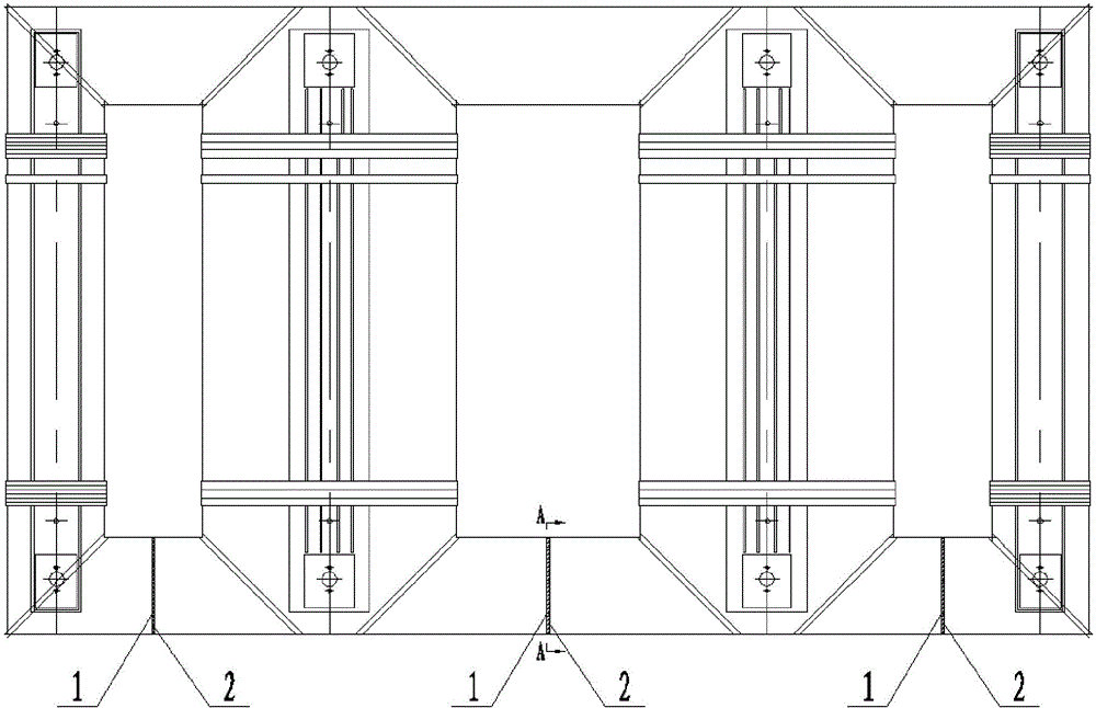
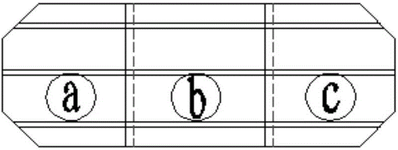
[0028] The present invention will be further elaborated below in conjunction with the accompanying drawings of the description.

[0029] Such as Figure 1~4 As shown, a high-current short-circuit test transformer with an air gap in the present invention has four iron core columns, and an air gap is left on the lower cross yoke between every two iron core columns, that is, the iron yoke air gap 1, and the iron core column An insulating plate 2 is filled in the yoke air gap 1, and a copper shield 3 is installed on the web corresponding to the iron yoke air gap 1; an insulating pull belt 4 that can support the insulating plate 2 is provided at the lower part of the iron yoke air gap 1; the insulating On the front and back sides of the plate 2, there are oil passages in the horizontal direction, and the oil passage groove direction of the insulating plate 2 is perpendicular to the stacking direction of the silicon steel sheet. The laid oil passages are connected; the silicon stee...


PUM


Abstract

The invention relates to a strong current short-circuit testing transformer with air gaps and an implementation method therefor. An air gap is formed in a lower transverse yoke between every two iron core limbs; the air gaps are filled with insulating plates; copper shield is mounted on a web plate corresponding to each air gap; the implementation method comprises the steps of fixing the copper shield on the inner side, corresponding to the position of each air gap, of the pre-processed web plate; horizontally placing a web plate with the copper shield on an iron core laminated plate platform; putting the insulating plates in a laminating process of iron cores, controlling the thickness of laminated sheets on the two sides of each air gap in the laminating process to be consistent and to be tightly adjacent to the corresponding insulating plates; placing a corresponding cushion block in the laminating process of the iron core sheets; after silicon steel sheets are laminated, mounting a web plate with the copper shield on the other side, and assembling a fastener on the corresponding iron core; and insulating an insulating pull band before erecting the corresponding iron core to ensure that the insulating plate in the air gap does not fall off when the corresponding iron core is erected. According to the transformer and the implementation method therefor, the iron core residual magnetism can be reduced; an iron core magnetic saturation phenomenon caused by excessive residual magnetism due to frequent short circuit of the testing transformer is lowered; and the output distortion of the test voltage and current waveform is avoided.

Description

technical field [0001] The invention relates to a transformer manufacturing technology, in particular to a high-current short-circuit test transformer with an air gap and a realization method thereof. Background technique [0002] At present, the high-current short-circuit test transformer is still an important power equipment in the high-current test station, mainly to provide short-circuit power for transformers, switches and other tested equipment. Some high-current test stations built in the 1970s, when selecting the magnetic density of test transformers, are the same as general power transformers, and the magnetic flux density reaches about 1.7 tesla, such as the strong current test station of France's Leiladi and Italy's CESI high-current laboratory. All the same. In the future transformer and switch tests, they found that the test voltage and current waveforms were distorted, and the reason was related to the selection of too high flux density and excessive residual ...

Claims


Application Information

Patent Timeline
Patent Type & Authority Applications(China)
IPC IPC(8): H01F27/24H01F3/14H01F27/36H01F38/00G01R31/00
Inventor 张东民方明臧丽娜王巍
Owner TBEA SHENYANG TRANSFORMER GRP CO LTD
Why Eureka
Eureka Blog
Learn More