System and method for monitoring optical cable of backbone network

A monitoring system and backbone network technology, applied in transmission systems, electromagnetic wave transmission systems, electrical components, etc., can solve problems such as low fault discrimination accuracy and failure to detect faults in time

Active Publication Date: 2016-04-13
STATE GRID CORP OF CHINA +2
View PDF3 Cites 14 Cited by
  • Summary
  • Abstract
  • Description
  • Claims
  • Application Information

AI Technical Summary

Problems solved by technology

[0007] The present invention provides a backbone network optical cable monitoring system and method to at least solve the problem that the existing passive test cannot find faults in time and the accuracy of fault discrimination is not high

Method used


Image

  • System and method for monitoring optical cable of backbone network
  • System and method for monitoring optical cable of backbone network
  • System and method for monitoring optical cable of backbone network

Examples


Embodiment Construction

[0028] The technical solutions in the embodiments of the present invention will be clearly and completely described below in conjunction with the accompanying drawings in the embodiments of the present invention. Obviously, the described embodiments are only some of the embodiments of the present invention, not all of them. Based on the embodiments of the present invention, all other embodiments obtained by persons of ordinary skill in the art without making creative efforts belong to the protection scope of the present invention.

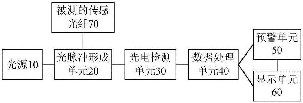
[0029] An embodiment of the present invention provides a backbone network optical cable monitoring system, figure 1 It is a structural block diagram of the backbone network optical cable monitoring system of the embodiment of the present invention, as figure 1 As shown, the system includes: a light source 10 , a light pulse forming unit 20 , a photoelectric detection unit 30 , a data processing unit 40 , an early warning unit 50 and a display unit ...


PUM


Abstract

The invention discloses a system and a method for monitoring an optical cable of a backbone network. The system comprises a light source, an optical pulse forming unit, a photoelectric detection unit, a data processing unit, an early warning unit and a display unit; the optical pulse forming unit is used for generating local oscillation light and pulsed light according to the light emitted by the light source, the pulsed light is transmitted to a measured sensing optical cable, and backward Rayleigh scattering light generated by the pulsed light in a propagation process is sent to the photoelectric detection unit together with the local oscillation light; the photoelectric detection unit is used for carrying out coherent detection on the backward Rayleigh scattering light and the local oscillation light; the data processing unit is used for carrying out data processing on the signal output by the photoelectric detection unit and outputting a monitoring result; the early warning unit is used for carrying out fault early warning according to the monitoring result; and the display unit is used for displaying a map and locating the fault position according to the map and the monitoring result, and the map comprises a backbone network circuit and an optical cable. The system and the method disclosed by the invention are used for actively monitoring the performance of the optical cable in real time, finding faults or hidden trouble in time and carrying out fault locating and fault early warning.

Description

technical field [0001] The invention relates to the technical field of optical cable monitoring, in particular to a backbone network optical cable monitoring system and method. Background technique [0002] At present, the radio and television network (group) companies in various provinces and cities in my country have basically built their own urban backbone optical cable networks covering core users. Compared with traditional telecommunication, wireless and other means of communication, optical fiber communication technology has unparalleled advantages, that is, large communication capacity, long relay distance, good confidentiality performance, and strong adaptability, but this large capacity and long distance At present, most of the optical cable transmission network in the radio and television system is maintained and managed through simple line inspection and emergency fault repair. With the gradual increase of fusion breakpoints, the performance of the optical cable t...

Claims


Application Information

Patent Timeline
Patent Type & Authority Applications(China)
IPC IPC(8): H04B10/077
CPCH04B10/0773
Inventor 赵旷怡李莉王刚吴润泽申惠琪万莹刘丽刘素伊聂文海黄毅臣李红建李顺昕王泉彭柏张立斌常海娇尤新雨吴立文范士清姚学科张恩江敖翠玲傅守强朱正甲张嵩高杨许颖孙密许文秀
Owner STATE GRID CORP OF CHINA
Why Eureka
Try Eureka