Power driving circuit of LED
A technology of power drive circuit and filter capacitor, applied in the field of dimming control of LED lamps, can solve problems such as inability to use normally and cannot be supported, and achieve the effects of low overall cost, reduced process requirements, and good compatibility
- Summary
- Abstract
- Description
- Claims
- Application Information
AI Technical Summary
Problems solved by technology
Method used
Image

Examples
Embodiment Construction
[0014] In order to make the object, technical solution and advantages of the present invention clearer, the present invention will be further described in detail below in conjunction with the accompanying drawings and embodiments. It should be understood that the specific embodiments described here are only used to explain the present invention, not to limit the present invention.
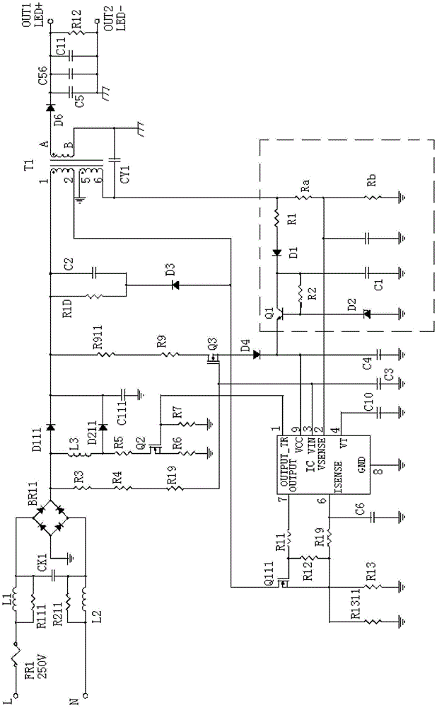
[0015] The embodiment of the present invention stabilizes the IC power supply voltage in the power drive circuit so that it is not affected by the change of the LED load, thereby ensuring that the power drive circuit can work normally; the compatibility of the power drive circuit with LED lights Better, the process requirements of LED are reduced, the overall cost of the lamp is lowered, and it has a good market prospect.
[0016] The specific realization of the present invention is described in detail below in conjunction with specific embodiment:
[0017] Such as figure 2 As shown, the LED pow...
PUM
 Abstract
Description
Claims
Application Information
 - Generate Ideas
- Intellectual Property
- Life Sciences
- Materials
- Tech Scout
- Unparalleled Data Quality
- Higher Quality Content
- 60% Fewer Hallucinations
Browse by: Latest US Patents, China's latest patents, Technical Efficacy Thesaurus, Application Domain, Technology Topic, Popular Technical Reports.
© 2025 PatSnap. All rights reserved.Legal|Privacy policy|Modern Slavery Act Transparency Statement|Sitemap|About US| Contact US: help@patsnap.com