Shock insulation type copper rod cutting machine

A technology of cutting machine and copper rod, which is applied in the direction of nibbling cutting device, shearing device, metal processing machinery parts, etc., can solve the problems of time-consuming, laborious, low efficiency, etc., and achieve convenient efficiency and good shock isolation effect Effect

Inactive Publication Date: 2016-04-20
XINXING PIPES ZHEJIANG COPPER
View PDF12 Cites 13 Cited by
  • Summary
  • Abstract
  • Description
  • Claims
  • Application Information

AI Technical Summary

Problems solved by technology

[0003] The invention provides a shock-isolated copper rod cutting machine, which solves th...

Method used


Image

  • Shock insulation type copper rod cutting machine
  • Shock insulation type copper rod cutting machine
  • Shock insulation type copper rod cutting machine

Examples


Embodiment 1

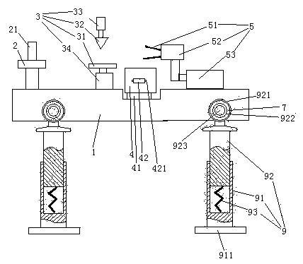
[0028] Embodiment one, see figure 1 , a shock-isolation type copper rod cutting machine, comprising a frame 1. A tray 2, a shearing device 3, a collection bucket 4 and a wire pulling device 5 are sequentially arranged on the frame 1 from left to right.

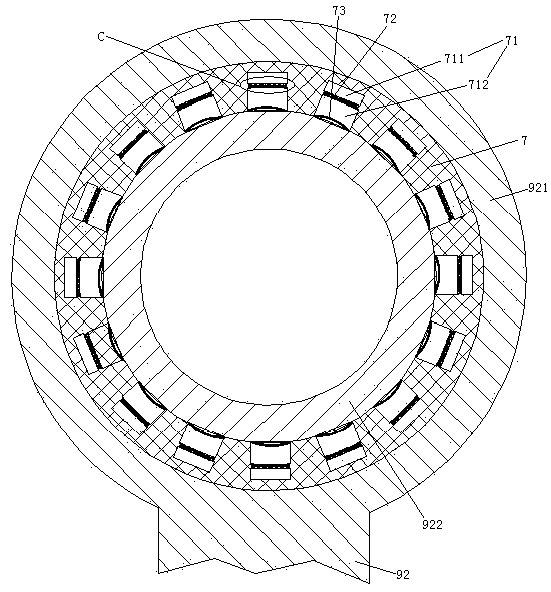
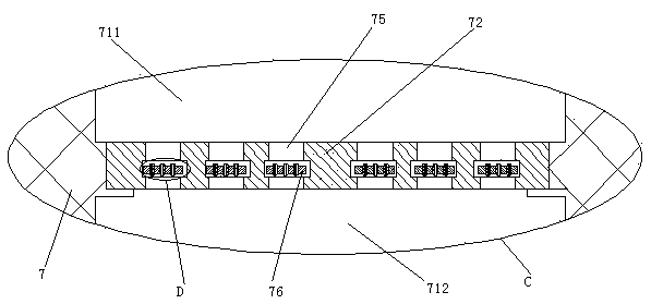
[0029] The frame 1 is provided with four mounting feet 9 . The mounting foot 9 includes a lower section 91 and an upper section 92 . The lower end of the lower section 91 is provided with a mounting seat 911 . The upper end of the lower section 91 is slidably sleeved on the lower end of the upper section 92 . The lower section 81 is provided with a damping spring 93 supporting the upper section 92 . The upper end of the upper section 92 is provided with a connecting ring 921 . An inner ring 922 passes through the connecting ring 921 . The inner ring 922 is connected with the connecting ring 921 through the rubber ring 7 . The inner ring 922 is pierced with connecting pins 923 . The connecting pin 923 is connected with ...

Embodiment 2

[0045] Embodiment two, the difference with embodiment one is:

[0046] see Figure 8 , The mounting foot 9 is also provided with a second driving mechanism 6 . The inner ring 922 is rotatably connected to the rubber ring 7 , and the rubber ring 7 is fixedly connected with the connecting ring 921 .

[0047] The second drive mechanism 6 includes a ratchet 61 , a pawl 62 for driving the ratchet, and a drive rod 63 . The ratchet 61 is coaxially connected with the inner ring 922 . The ratchet 61 is integrated with the inner ring 922 . The pawl 62 is fixedly connected to one end of the driving rod 63 . The upper section 92 is provided with a sliding hole 924 . The other end of the driving rod 63 can slide through the sliding hole 924 two-dimensionally. The lower end of the drive rod 63 is slidably hooked to the lower section 91 along the radial direction of the connecting ring 921 (see figure 1 ) and connected with the next paragraph. The driving rod 63 is provided with a st...


PUM


Abstract

The invention relates to cutting equipment. A shock insulation type copper rod cutting machine comprises a tray, a shearing device and a line drawing device which are sequentially arranged on a rack; the tray is connected to the rack in a rotational manner, and an insertion rod is arranged on the tray; the shearing device comprises a cutting board, a cutting knife located above the cutting board and a cutting air cylinder for driving the cutting knife to ascend and descend; the line drawing device comprises a line clamp, a finger clamping air cylinder for driving the line lamp to open and close and a line drawing oil cylinder for driving the finger clamping air cylinder to open and close relative to the shearing device; an installation pin is arranged on the rack and comprises an upper section and a lower section, the lower end of the upper section is sleeved with the upper end of the lower section, an installation base is arranged at the lower end of the lower section, a damping spring for supporting the upper section is arranged in the lower section, and a connecting ring is arranged at the upper end of the upper section; and an inner ring is arranged in the connecting ring in a penetrating manner and connected with the connecting ring together through a rubber ring, and a connecting pin connected to the rack is arranged on the inner ring in a penetrating manner. According to the shock insulation type copper rod cutting machine, the problems that when a waste copper rod is manually cut, time and labor are wasted, and the efficiency is low are solved.

Description

technical field [0001] The invention relates to cutting equipment, in particular to a vibration-isolation type copper rod cutting machine. Background technique [0002] In the production process of copper rods, more or less rolls of scrap copper rods will be produced, which requires the waste copper rods to be returned to the furnace and then melted to produce finished products. The rolled copper rods cannot be returned directly to the furnace and need to be cut off. Reheat. Existing truncation of waste copper rods is done manually through a section of the shearing device, which causes a great waste of labor and low work efficiency. A shearing device is disclosed in the patent document with the Chinese patent application No., the date of publication being March 6, 2002, and the name "Supply and Exhaust Energy-saving Plastic Wire Drawing Machine". Contents of the invention [0003] The invention provides a shock-isolation type copper rod cutting machine, which solves the ...

Claims


Application Information

Patent Timeline
IPC IPC(8): B23D27/00B23D33/02B23Q11/00
CPCB23D27/00B23D33/02B23Q11/0032
Inventor 杨鑫何海军翟建民陈宗华孙冀阳张斌海刘娜
Owner XINXING PIPES ZHEJIANG COPPER
Why Eureka
Try Eureka