Feeding mechanism

A coil and screw technology, which is applied to metal processing machinery parts, feeding devices, other manufacturing equipment/tools, etc., can solve the problem of increased labor intensity, and achieve the effect of saving time and effort in operation, convenient production and reducing resistance.

Pending Publication Date: 2016-04-20
CHONGQING YUKUNLONG METALLURGICAL MATERIAL CO LTD
View PDF0 Cites 3 Cited by
  • Summary
  • Abstract
  • Description
  • Claims
  • Application Information

AI Technical Summary

Problems solved by technology

[0003] The present invention intends to provide a feeding mechanism to solve the problem of increased la

Method used


Image

  • Feeding mechanism
  • Feeding mechanism
  • Feeding mechanism

Examples


Embodiment Construction

[0019] The present invention will be described in further detail below by means of specific embodiments:

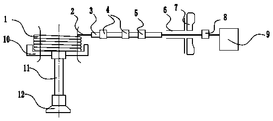
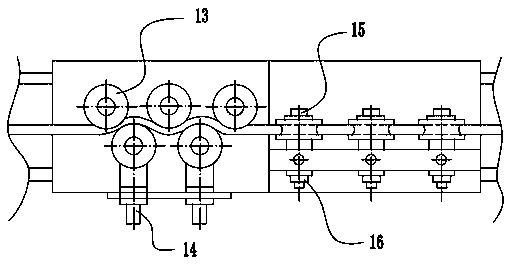
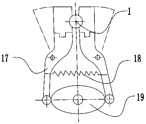
[0020] The reference signs in the drawings of the description include: coil material 1, feed screw rod 2, slide plate 3, straightening mechanism 4, front chuck 5, rotary knife holder 6, blade 7, rear chuck 8, motor 9, support Disk 10, support rod 11, support seat 12, first roller 13, first adjustment screw 14, second roller 15, second adjustment screw 16, jaw 17, first spring 18, first cam 19, fixed Block 20, slide block 21, lever 22, second cam 23, stop block 24, second spring 25.

[0021] Such as figure 1 As shown, a feeding mechanism includes a support plate 10 for supporting and holding the coil material 1, the support plate 10 is screwed to a telescopic rod 11, the telescopic rod 11 is connected to a support seat 13, and the telescopic rod 11 is an electric telescopic rod. When feeding, the telescopic rod 11 is connected with the motor 9, and the telescopic rod 11 ...


PUM


Abstract

The invention discloses a feeding mechanism and relates to the field of auxiliary machining. The feeding mechanism comprises a supporting frame and further comprises a motor and a feeding screw connected with the motor. A straightening mechanism, a front chuck, a rotary knife and a rear chuck are sequentially arranged on the feeding screw. A sliding plate is arranged on the feeding screw and slidably connected to the feeding screw. The straightening mechanism and the front chuck are fixedly connected to the sliding plate. The supporting frame comprises a supporting tray, a telescopic supporting rod and a supporting base, wherein the supporting tray is used for containing roll materials, the telescopic supporting rod is connected with the supporting tray, and the supporting base is connected with the supporting rod. By the adoption of the feeding mechanism, the labor intensity of carrying the roll materials during feeding can be relieved.

Description

technical field [0001] The invention relates to the field of auxiliary processing, in particular to a feeding mechanism. Background technique [0002] In the processing field, coils rolled into cylindrical shapes are now commonly used as storage forms for raw materials. The reason why the raw materials in the form of rolls is very popular is that under the same space conditions, the most raw materials can be rolled up and stored in the form of rolls. Due to this characteristic of the roll material, each roll of unopened roll material is very heavy. When it is necessary to use the coil material, it is often necessary to use tools to move the coil material. Especially in the situation that many machines are used for loading materials now, heavy coils must be transported to the corresponding positions of the feeding mechanism before processing and loading. This not only leads to an increase in labor intensity, but also may cause certain safety hazards during the handling pro...

Claims


Application Information

Patent Timeline
IPC IPC(8): B23P23/04B23Q7/00B23Q7/04B23Q5/40B21D1/02
CPCB23P23/04B21D1/02B23Q5/402B23Q7/00B23Q7/043
Inventor 罗静李炎清王学清
Owner CHONGQING YUKUNLONG METALLURGICAL MATERIAL CO LTD
Why Eureka
Try Eureka