Cast tube inner wall cleaning device

A technology for cleaning devices and casting pipes, which is applied in the direction of used abrasive processing devices, explosion generating devices, and abrasive feeding devices, etc., which can solve problems such as short replacement cycles, affect production rhythm, and increase steel grit consumption, etc., to achieve Reduce the loss of steel grit, do not affect the production rhythm, and achieve significant economic benefits

Inactive Publication Date: 2016-04-20
DALIAN JIAOTONG UNIVERSITY
View PDF9 Cites 1 Cited by
  • Summary
  • Abstract
  • Description
  • Claims
  • Application Information

AI Technical Summary

Problems solved by technology

At present, the problems existing in the cleaning of the inner wall of the ductile iron pipe are mainly manifested in the following aspects: First, the inner wall of the cast pipe is usually cleaned manually, which is labor-intensive, inefficient and ineffective; secondly, the mechanical cleaning method The shot blasting device commonly used in the industry is to use the mechanical centrifugal force to throw out the steel grit. The operation is complicated, the steel grit wears faster, and the replacement cycle is short, which not only increases the labor intensity of the workers, but also affects the production rhythm; in terms of quality , the original cleaning effect is relatively poor, and the roughness requirements cannot be met, which affects the adhesion of the inner wall; in terms of cost, multiple cleanings increase the consumption of steel grit, thereby increasing the cost

Method used


Image

  • Cast tube inner wall cleaning device

Examples


Embodiment Construction

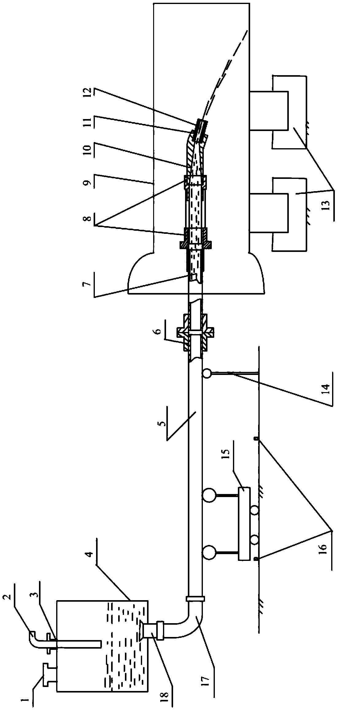
[0021] As shown in the accompanying drawings, the cast pipe inner wall cleaning device includes a sealed tank 4, a steel pipe 5, a shaft coupling 6, a spray gun head, a support roller group 13, a support frame 14 and a mobile trolley 15; The upper part is processed with a sand inlet 1 and a nitrogen inlet 2; the lower part of the sealed tank 4 is equipped with a nitrogen outlet 18; the nitrogen outlet 18 is connected to the steel pipe 5 through a hose 17; the steel pipe 5 is connected to the spray gun through a coupling 6 The nozzle part of the spray gun head extends into the cast pipe 9 on the upper part of the support roller group 13; the end of the steel pipe 5 near the coupling is supported by the support frame 14, and the middle part is supported by the mobile trolley 15 and moves along with it. The moving trolley 15 advances and retreats; the steel grit 7 is blown from the steel pipe into the spray gun head through the nitrogen flow, and then blown out by the spray gun he...


PUM


Abstract

The invention provides a cast tube inner wall cleaning device and relates to cast tube inner wall cleaning equipment, in particular to a spherulitic graphite cast tube inner wall gas type cleaning device. The cast tube inner wall cleaning device comprises a sealing tank, a steel tube, a coupler, a spray gun head, a supporting roller set, a supporting rack and a movable trolley. A sand inlet and a nitrogen inlet are processed in the upper portion of the sealing tank. A nitrogen outlet is formed in the lower portion of the sealing tank. The nitrogen outlet is connected with the steel tube through a hose. The steel tube is connected with the spray gun head through the coupler. A gun nozzle part of the spray gun head extends into a cast tube erected on the upper portion of the supporting roller set. The end, close to the coupler, of the steel tube is supported by the supporting rack. Meanwhile, the middle of the steel tube is supported by the movable trolley and moves forwards and backwards along with the movable trolley. Steel emery is blown into the spray gun head from the steel tube through nitrogen flow, then blown out of the spray gun head and knocked on the inner wall of the cast tube, and the cleaning function is achieved. The cast tube inner wall cleaning device has the advantages of being novel in structure, easy and convenient to operate, low in machining cost, capable of reducing labor intensity of workers and improving work efficiency, obvious in cleaning effect and the like.

Description

technical field [0001] The device for cleaning the inner wall of a cast pipe according to the present invention relates to a device for cleaning the inner wall of a cast pipe, in particular to a gas type cleaning device for the inner wall of a nodular cast pipe. Background technique [0002] At present, in the domestic centrifugal cast iron pipe production plants, cleaning the inner wall of the ductile iron pipe is an essential task. The smoother the inner wall of the cast pipe and free of impurities, the more conducive to the smooth flow of the pipeline. At present, the problems existing in the cleaning of the inner wall of the ductile iron pipe are mainly manifested in the following aspects: First, the inner wall of the cast pipe is usually cleaned manually, which is labor-intensive, inefficient and ineffective; secondly, the mechanical cleaning method The shot blasting device commonly used in the industry is to use the mechanical centrifugal force to throw out the steel g...

Claims


Application Information

Patent Timeline
Patent Type & Authority Applications(China)
IPC IPC(8): B24C3/32B24C9/00B24C7/00B24C5/04
CPCB24C3/325B24C5/04B24C7/0046B24C9/00
Inventor 宋雪萍陈勇张连东
Owner DALIAN JIAOTONG UNIVERSITY
Why Eureka
Try Eureka