Traction beam

The technology of traction beam and reinforcing beam is applied in the field of rail car body manufacturing, which can solve the problems of complicated installation and connection between the traction beam and the coupler, unfavorable lightweight design of the car body, and large own weight, and achieves reasonable force transmission and reduction of welding heat input. , The effect of reducing the difficulty of processing

Inactive Publication Date: 2016-04-20
CRRC QINGDAO SIFANG CO LTD
View PDF8 Cites 2 Cited by
  • Summary
  • Abstract
  • Description
  • Claims
  • Application Information

AI Technical Summary

Problems solved by technology

However, in order to achieve a reliable connection between the existing draw beam structure and the draw beam, its structure is complex and its own weight is large, which is not conducive to the lightweight design of the car body and the improvement of the running speed of the train. At the same time, there are also complicated installation and connection between the draw beam and the coupler. The problem

Method used


Image

  • Traction beam
  • Traction beam
  • Traction beam

Examples


Embodiment Construction

[0034] The drawing beam of the present invention will be described below in conjunction with the accompanying drawings.

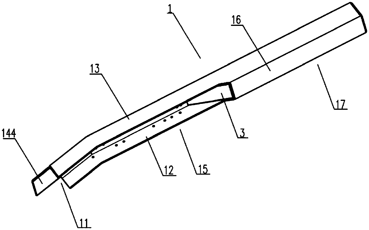
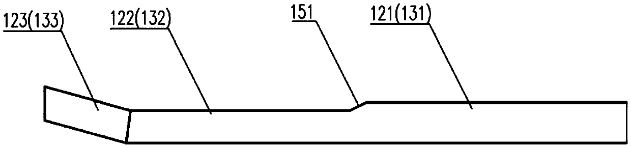
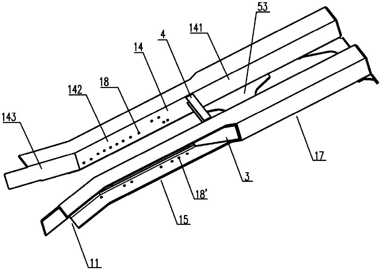
[0035] Such as Figure 1-4 As shown, the traction beam of the present invention includes two traction beam single pieces 1 arranged side by side, and the front ends of the two traction beam single pieces 1 are respectively provided with bending parts 11 bent in opposite directions, so that The front end of the traction beam forms a bell mouth 2 , the front end of the traction beam 1 is connected to the vehicle body buffer beam 7 , and its rear end is connected to the corbel 8 .

[0036] Preferably, the front end of the traction beam 1 is welded to the vehicle body buffer beam 7 , and its rear end is welded to the corbel 8 .

[0037] In a preferred embodiment of the present invention, the traction beam single piece 1 is an integrally formed structure.

[0038] More preferably, the single part of the traction beam is a full-length 6-series welded profile, m...


PUM


Abstract

The invention provides a traction beam which comprises two traction beam single pieces arranged side by side, wherein bent parts which are bent in opposite directions are respectively arranged at the front ends of the traction beam single pieces, so that a horn-shaped opening is formed in the front end of the traction beam; the front end of the traction beam is connected with a vehicle body buffering beam, and the rear end of the traction beam is connected with a sleeper beam. According to the traction beam, the vehicle body sleeper beam is safely connected with the buffering beam, so that the requirement for the intensity of the vehicle body is met; the horn-shaped opening structure is arranged at the front end of the traction beam, so that the requirement on a rotating angle of a vehicle hook is met; a vehicle hook mounting seat is connected with the traction beam through a rivet; due to welding heat input, the safety is improved; under the reinforcement action of a reinforcement plate, the structure of the traction beam is safer and more reliable; the traction beam single piece is made of a full 6-series opening-type profile, so that the anti-stress and anti-corrosion comparison is more outstanding; by the use of the full profile, the processing difficulty is reduced; by the adoption of welding of the profile and a plate, the weight reducing requirement is considered, and enough intensity can be met.

Description

technical field [0001] The invention relates to the field of rail vehicle body manufacturing, in particular to a draw beam structure applied to rail vehicles. Background technique [0002] With the rapid popularization and promotion of domestic urban rail transit, higher design and use requirements are put forward for the traction beam which constitutes the main part of the drive system. [0003] Among them, the traction beam used in light rail trains and subways is the central component that connects and transmits the driving force of the bogie to the car body, and is also the key equipment for power transmission to achieve fast and safe driving of the vehicle. The traction beam is an important force-bearing part in the car body structure, mainly connecting the car body buffer beam and the corbel, and also needs to meet the requirements for the installation of the coupler. However, in order to achieve a reliable connection between the existing draw beam structure and the d...

Claims


Application Information

Patent Timeline
Patent Type & Authority Applications(China)
IPC IPC(8): B61F5/02
CPCB61F5/02
Inventor 林庆琳孙现亮陈书翔田爱琴丁叁叁李吉春郑伟寇福俊龚明孙彦彬
Owner CRRC QINGDAO SIFANG CO LTD
Why Eureka
Try Eureka