
A bobbin tail yarn processing device and processing method

A technology for processing equipment and tail yarns, which is applied in the direction of thin material handling, delivery of filamentous materials, transportation and packaging, etc. It can solve problems such as incomplete removal of tail yarns, deformation of the hanging spindle conveyor chain, and influence on roving winding, etc., to achieve Achieve automatic cleaning, simple and compact structure, and save manpower

Active Publication Date: 2018-04-24
QINGDAO TIANYI GROUP RED FLAG TEXTILE MACHINERY +1
View PDF14 Cites 0 Cited by
  • Summary
  • Abstract
  • Description
  • Claims
  • Application Information

AI Technical Summary

Problems solved by technology

The device adopts the combination of bobbin lifting transmission device, suction nozzle lifting transmission device, cleaning device and capping device, which can automatically remove the tail yarn from the bobbin hoisted by the spindle hanger, which is used to replace the manual removal of the tail yarn on the roving bobbin However, the structure of the device is very complicated, and the production cost is high. During the process of removing the tail yarn, the bobbin is not removed from the hanging spindle, and the cleaning process will cause the shaking of the hanging spindle, which will lead to deformation of the hanging spindle conveying chain in the long run; In addition, the tail yarn wound at the position of the velvet tape on the upper part of the bobbin is often not removed, and the tail yarn is not completely removed, which will still affect the winding of the later roving

Method used


Image

  • A bobbin tail yarn processing device and processing method
  • A bobbin tail yarn processing device and processing method
  • A bobbin tail yarn processing device and processing method

Examples


Embodiment Construction

[0032] The present invention will be further described in detail below in conjunction with the accompanying drawings and specific embodiments, but the present invention is not limited to these embodiments.

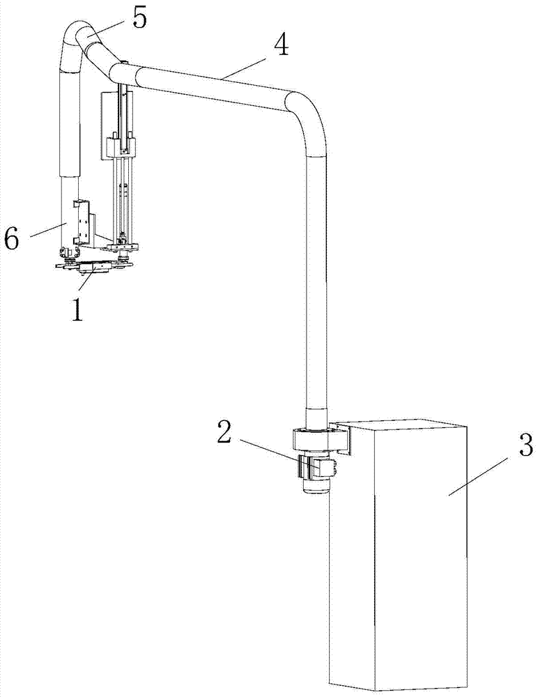
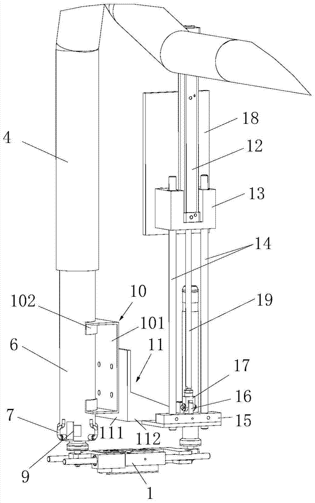
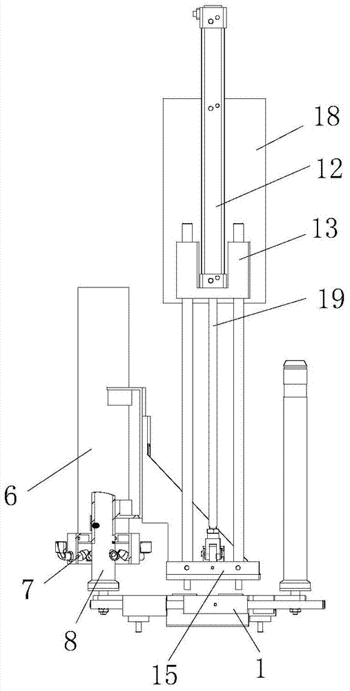
[0033] Such as Figure 1 to Figure 3 As shown, a bobbin tail yarn processing equipment includes a switch 1 and a tail yarn clearing device, an empty yarn bobbin 8 withdrawn from the spinning frame is vertically placed on the switch 1, and the tail yarn clearing device includes an air duct 4, which is arranged on The suction fan 2 at the end of the air duct 4, the cover tube 6 capable of wrapping the empty yarn tube 8 and the lifting mechanism that drives the cover tube 6 to move up and down, the air tube 4 is connected with the cover tube 6, and the diameter of the cover tube 6 is smaller than that of the air duct 4, when the cover tube 6 moves up and down, it moves along the diameter of the air duct 4, and the corners of the air duct 4 are provided with corrugated hoses 5...


PUM


Abstract

The invention discloses a bobbin tail yarn treatment device comprising an exchanger and a tail yarn removing device, wherein empty bobbins retreated from a spinning frame are vertically arranged on the exchanger; the tail yarn removing device comprises an air pipe, a suction ventilator arranged at the tail end of the air pipe, cover pipes capable of covering empty bobbins, and a lifting mechanism which can be used for driving the cover pipes to do up and down movement; the air pipe is communicated with the cover pipes; the lower parts of the cover pipes are provided with a plurality of air spraying pipes; air inlet ends of the air spraying pipes are positioned at the outer sides of the cover pipes and are connected with an external air source; the air outlet ends of the air spraying pipes are positioned in the inner sides of the cover pipes and face the inclined up parts of the cover pipes; the lower parts of the cover pipes are provided with a plurality of correlation photoelectric sensors. The invention also discloses a bobbin tail yarn treatment method in which the bobbin tail yarn treatment device is used for performing tail yarn removing on the empty bobbins from bottom to up, so that the thorough removing of tail yarns is ensured. By using the bobbin tail yarn treatment device and method, the automatic removing of the tail yarns is realized, and the production efficiency is greatly improved.

Description

technical field [0001] The invention belongs to the field of textile machinery, and in particular relates to bobbin tail yarn processing equipment and a processing method. Background technique [0002] After the spinning frame is finished spinning, the bobbin withdrawn from the spinning frame needs to be transferred to the roving frame for use in the roving frame. There is tail yarn on the bobbin withdrawn from the spinning frame, and if the tail yarn is not removed, it will affect the winding of the roving. [0003] The patent application with the application number 201510561552.4 discloses a roving tail yarn processing device, which includes a bobbin lifting transmission device, a suction nozzle lifting transmission device and a capping device. Tube lifting mechanism, each bobbin lifting mechanism includes a housing on the frame, a sleeve is arranged in the housing, a lifting rod is arranged in the sleeve, the lifting rod can rotate with the sleeve, and the upper end of th...

Claims


Application Information

Patent Timeline
Patent Type & Authority Patents(China)
IPC IPC(8): B65H73/00
CPCB65H73/00B65H2406/30
Inventor 冯文成吴海艳黄金芳赵付斌
Owner QINGDAO TIANYI GROUP RED FLAG TEXTILE MACHINERY
Learn More