Speed-adjustable high-thrust hydraulic lifting table

A technology of hydraulic lifting and high thrust, applied in lifting devices, fluid pressure actuating devices, servo motor components, etc., can solve the problem of difficulty in ensuring the smooth operation of the lifting platform, inability to adjust the moving speed of the lifting platform, and not suitable for large flow occasions, etc. problems, to achieve the effect of improving work stability and energy utilization, spool movement is sensitive and fast, and leakage is small.

Inactive Publication Date: 2016-04-20
NINGBO INST OF TECH ZHEJIANG UNIV ZHEJIANG
View PDF8 Cites 12 Cited by
  • Summary
  • Abstract
  • Description
  • Claims
  • Application Information

AI Technical Summary

Problems solved by technology

[0005] The reversing valve used in the existing hydraulic lifting platform is usually in the form of a spool valve, and the reversing valve in the form of a spool valve has poor flow capacity and is not suitable for large flow occasions
The reversing valve in the form of a slide valve realizes the conversion of the oil flow direction through the linear reciprocating movement of the spool. During the reversing process, the unbalanced reciprocating speed of the spool will easily cause the piston movement of the hydraulic cylinder to be unstable, that is, it is difficult to ensure the lifting Smooth operation of the platform
In addition, the oil supply system of the hydraulic lifting platform often supplies oil to the hydraulic cylinder with a constant flow rate, and the moving speed of the lifting platform cannot be adjusted according to the actual situation.

Method used


Image

  • Speed-adjustable high-thrust hydraulic lifting table
  • Speed-adjustable high-thrust hydraulic lifting table
  • Speed-adjustable high-thrust hydraulic lifting table

Examples


Embodiment Construction

[0031] The following will clearly and completely describe the technical solutions in the embodiments of the present invention with reference to the accompanying drawings in the embodiments of the present invention. Obviously, the described embodiments are some of the embodiments of the present invention, but not all of them. Based on the embodiments of the present invention, all other embodiments obtained by persons of ordinary skill in the art without making creative efforts belong to the protection scope of the present invention.

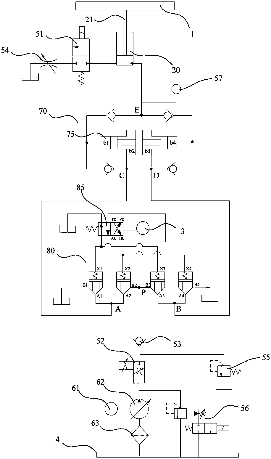
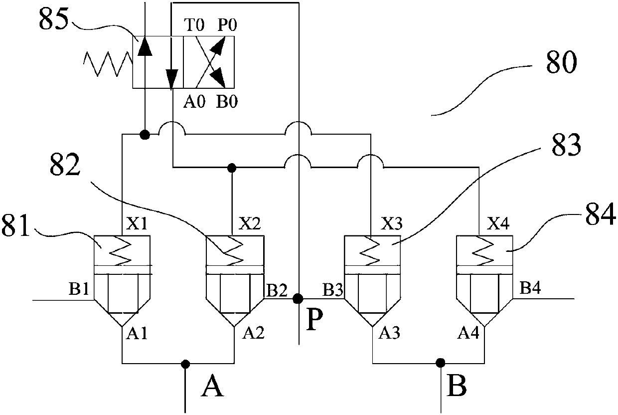
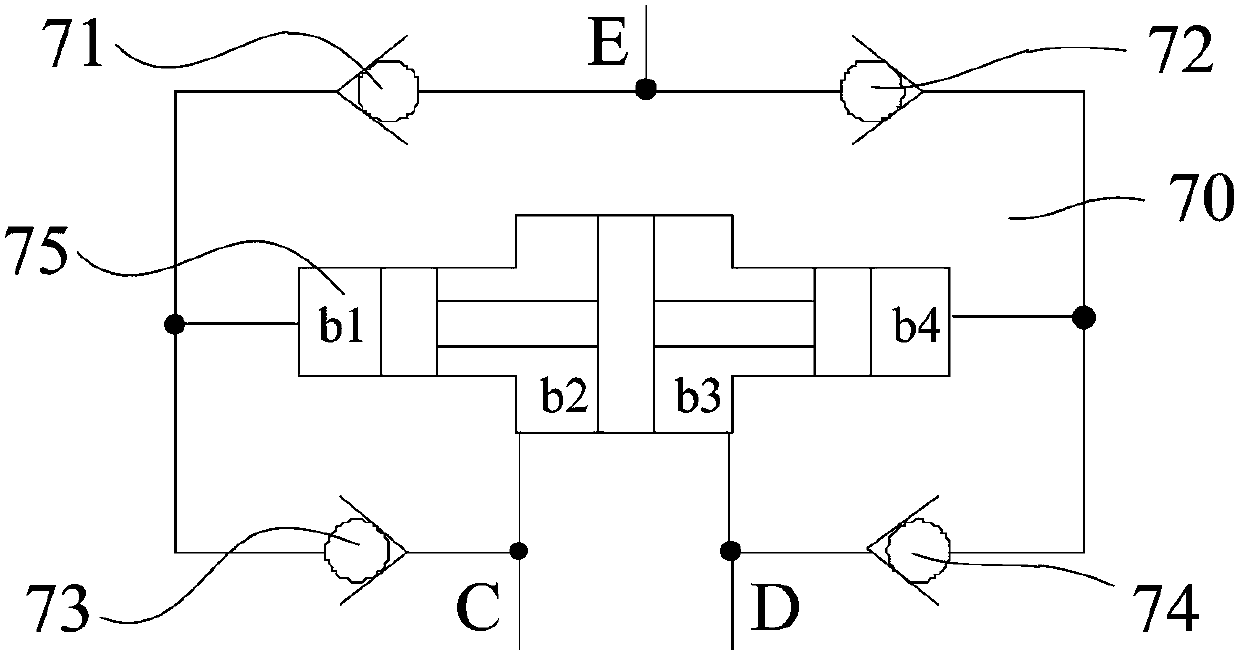
[0032] refer to Figure 1 to Figure 3 , figure 1 The working principle diagram of an embodiment of an adjustable-speed high-thrust hydraulic lifting platform is shown in . From figure 1It can be seen from the figure that the adjustable-speed high-thrust hydraulic lifting platform includes a lifting platform 1, a hydraulic cylinder 20, a stepping motor 3, an oil supply system, a controller, an oil tank 4, a two-position two-way reversing valve 51...


PUM


Abstract

The invention relates to a speed-adjustable high-thrust hydraulic lifting table. The speed-adjustable high-thrust hydraulic lifting table comprises a lifting platform, a hydraulic cylinder, a control valve group, an oil supply system, a controller, an oil tank, a speed adjusting valve, a booster, a two-position two-way reversing valve and a stepper motor; the lifting platform is connected to a push rod of the hydraulic cylinder; and the oil supply system can suck oil from the oil tank and supply the oil to the hydraulic cylinder. The oil supply system supplies the oil to the hydraulic cylinder via the speed adjusting valve, the control valve groupand the booster in sequence; and the controller is electrically connected with the two-position two-way reversing valve, the stepper motor, the speed adjusting valve and the oil supply system. The hydraulic lifting table has two characteristics of adjustable moving speed of the lifting platform and large thrust supplied by the hydraulic cylinder. In addition, the control valve group consisting of a valve element rotary reversing valve and cartridge valves is used for replacing a slide valve, the conversion of oil flowing directions of the hydraulic system can be realized, and the circulating capacity is greater, so that the lifting table is suitable forhigh-flow places.

Description

technical field [0001] The invention relates to a lifting device, in particular to an adjustable-speed and high-thrust hydraulic lifting platform. Background technique [0002] Lifting platform is a kind of machinery for transporting people or objects vertically, which is widely used in cargo transportation at different heights, high-altitude installation and maintenance and other operations. According to the different structures, the lifting platform can be divided into scissor lifting platform, guide rail lifting platform, aluminum alloy lifting platform and cylinder lifting platform. [0003] According to different driving methods, the lifting platform can also be divided into a lifting platform based on a motor drive method, a wave maker based on a pneumatic drive method, and a lifting platform based on a hydraulic drive method. The lifting platform based on the motor drive mode has a weak load capacity due to the small torque output of the motor; if the lifting platfor...

Claims


Application Information

Patent Timeline
Patent Type & Authority Applications(China)
IPC IPC(8): B66F11/04F15B13/02
Inventor 刘毅戚凯科齐宇龚国芳
Owner NINGBO INST OF TECH ZHEJIANG UNIV ZHEJIANG
Why Eureka
Try Eureka