
Electrostatic spinning machine

An electrospinning machine and spinning solution technology, applied in the field of electrospinning machines, can solve problems such as uneven fiber thickness, achieve the effects of reducing anisotropy, improving the uniformity of fiber thickness and fiber quality

Active Publication Date: 2016-04-20
JIANGXI INST OF FASHION TECH
View PDF10 Cites 17 Cited by
  • Summary
  • Abstract
  • Description
  • Claims
  • Application Information

AI Technical Summary

Problems solved by technology

[0006] Therefore, the technical problem to be solved by the present invention is to overcome the defects of uneven thickness of the fibers produced by the electrospinning device in the prior art.

Method used


Image

  • Electrostatic spinning machine
  • Electrostatic spinning machine
  • Electrostatic spinning machine

Examples


Embodiment 1

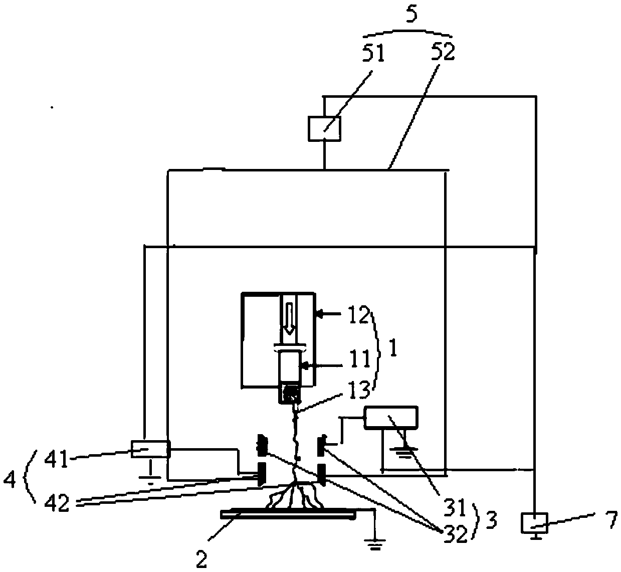
[0030] This embodiment provides an electrospinning machine such as figure 1 As shown, it includes: a spinning solution injection device 1; a fiber receiving device 2, which is arranged below the spinning solution injection device 1; the electrospinning machine also includes: an electric field generating device 3, including two The provided electrode plates 31 are distributed on both sides of the central axis between the spinning solution injection device 1 and the fiber receiving device 2; the magnetic field generating device 4 includes two magnetic pole plates 41 arranged vertically , distributed on both sides of the central axis; the first rotating device 5 is used to drive the magnetic pole plate 41 to rotate along the central axis.

[0031] In the electrospinning machine provided in this embodiment, by adding a magnetic field generating device and a first rotating device, the direction of the magnetic field is continuously changed around the central axis, thereby reducing ...

Embodiment 2

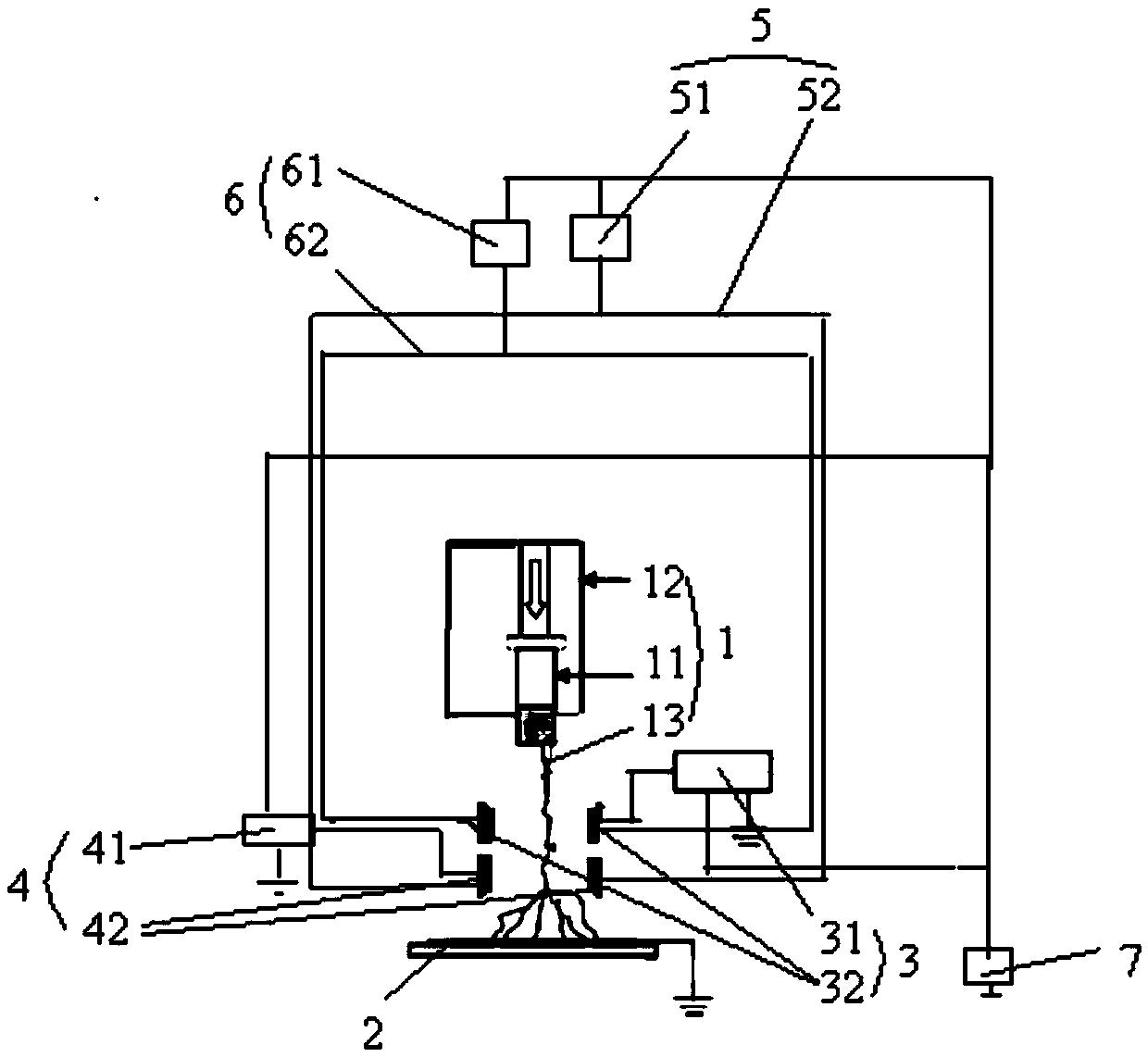
[0048] This embodiment provides an electrospinning machine, such as figure 2 As shown, it includes: a spinning solution injection device 1; a fiber receiving device 2, which is arranged below the spinning solution injection device 1; the electrospinning machine also includes: an electric field generating device 3, including two The provided electrode plates 31 are distributed on both sides of the central axis between the spinning solution injection device 1 and the fiber receiving device 2; the magnetic field generating device 4 includes two magnetic pole plates 41 arranged vertically , distributed on both sides of the central axis; the first rotating device 5 is used to drive the magnetic pole plate 41 to rotate along the central axis; the second rotating device 6 is used to drive the electrode plate 31 along the The central axis performs rotational movement.

[0049] In the electrospinning machine provided in this embodiment, by adding a second rotating device, the electro...


PUM

PropertyMeasurementUnit
Lengthaaaaaaaaaa

Abstract

The invention provides an electrostatic spinning machine which comprises a spinning solution spray device, a fiber receiving device, an electric field generation device, a magnetic field generation device and a first rotation device, wherein the fiber receiving device is arranged at the lower part of the spinning solution spray device; the electric field generation device comprises two electrode plates which are arranged along the vertical direction and are distributed at two sides of a central axis between the spinning solution spray device and the fiber receiving device; the magnetic field generation device comprises two magnetic pole plates which are arranged along the vertical direction and are distributed at two sides of the central axis; the first rotation device is used for driving the magnetic pole plates to carry out rotary motion along the central axis. According to the electrostatic spinning machine, through addition of the magnetic field generation device and the first rotation device, the magnetic field direction continuously changes around the central axis, so that the anisotropy in the fiber in the spinning process is lowered; and the fiber thickness average rate and the fiber quality are improved.

Description

technical field [0001] The invention relates to the technical field of electrostatic spinning, in particular to an electrostatic spinning machine. Background technique [0002] Wool fiber is a natural high-quality textile fiber material. It not only has high thermal performance, but also has the advantages of moisture absorption, softness and complete color spectrum, and is deeply loved by consumers. However, every year in our country, a large amount of low-quality wool, waste wool, and leftover wool are discarded because they cannot be used, resulting in a large waste of resources. [0003] With the maturity of electrospinning technology in recent years, technicians are currently trying to prepare wool fibers by dissolving waste wool and extracting wool keratin for electrospinning. However, because the spatial structure of wool keratin is an α-helical structure, in the traditional electrospinning process, due to the large surface tension of the spinning solution, the aniso...

Claims


Application Information

Patent Timeline
IPC IPC(8): D01D5/00
CPCD01D5/0061D01D5/0092
Inventor 林燕萍杨陈
Owner JIANGXI INST OF FASHION TECH
Learn More