A kind of flue gas system and its working method

A working method and flue gas technology, applied in the combustion method, induced draft, combustion equipment, etc., can solve problems such as difficulty in parallel operation of induced draft fans, increasing the complexity of flue gas system, and damage to boiler heating surface pipes.

Active Publication Date: 2018-02-27
NORTH CHINA ELECTRICAL POWER RES INST +1
View PDF4 Cites 0 Cited by
  • Summary
  • Abstract
  • Description
  • Claims
  • Application Information

AI Technical Summary

Problems solved by technology

[0008] like figure 2 The damper configured with the smoke and air system of the steam-driven induced draft fan has the following disadvantages: (1) If only one induced draft fan is running normally, and the other induced draft fan needs to resume operation, it is necessary to reduce the output of the induced draft fan (reduce the induced draft fan unit load), if the induced draft fan output is not reduced, it will be difficult to run the induced draft fans in parallel, and accidents will occur in serious cases, and the economy is poor
(2) When a boiler fire extinguishing accident occurs under the high-load state of the induced draft fan unit, it takes a long time for the steam-driven induced draft fan to coast (the process in which the motor speed begins to gradually decrease after power failure), and the steam-driven induced draft fan is shut down. During the process, the negative pressure of the furnace is greatly affected, and it is a kind of damage to the heating surface tube of the boiler.
[0012] use image 3 The damper configuration of the flue gas system shown in the figure, when one induced draft fan is in normal operation and the other induced draft fan needs to resume operation, although there is no need to reduce the output of the induced draft fan (reduce the load of the induced draft fan unit), the induced draft fans can be operated in parallel , but on the basis of the original flue gas system, the start-up adjustment doors A12 and B12, the start-up circulation flue door A04 and B04 and the related flue are added, which significantly increases the construction cost and increases the flue gas system. The complexity requires a large installation space

Method used


Image

  • A kind of flue gas system and its working method
  • A kind of flue gas system and its working method
  • A kind of flue gas system and its working method

Examples


Embodiment Construction

[0046] In order to make the object, technical solution and advantages of the present invention clearer, the present invention will be described in further detail below in conjunction with the embodiments and accompanying drawings. Here, the exemplary embodiments and descriptions of the present invention are used to explain the present invention, but not to limit the present invention.

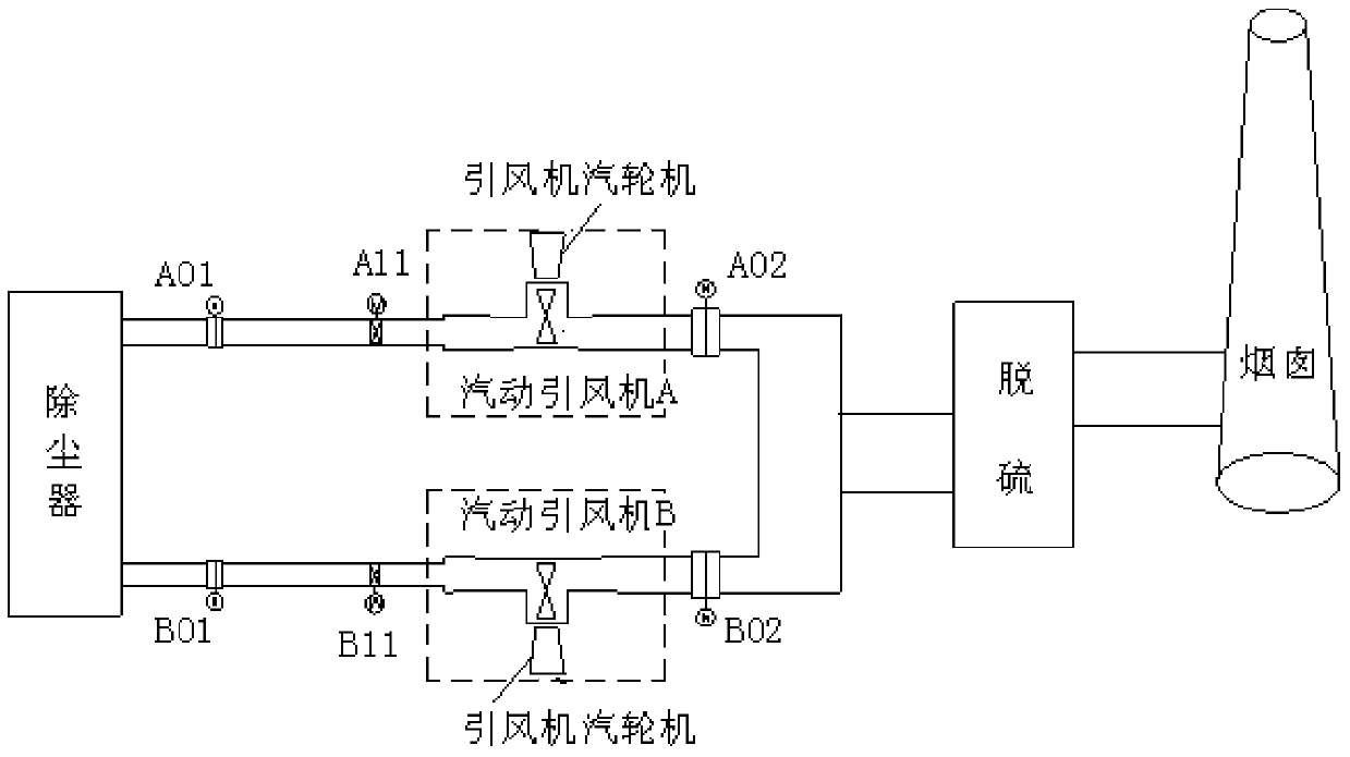
[0047] In the existing flue gas system, if according to image 3 The configuration of the damper for the flue gas system shown in the figure will significantly increase the construction cost and complexity of the flue gas system, and requires a large installation space. In view of this problem, the present invention proposes a flue gas system with a start-up bypass, which does not significantly increase the construction cost, does not increase the complexity of the flue gas system, and does not require a large installation space.

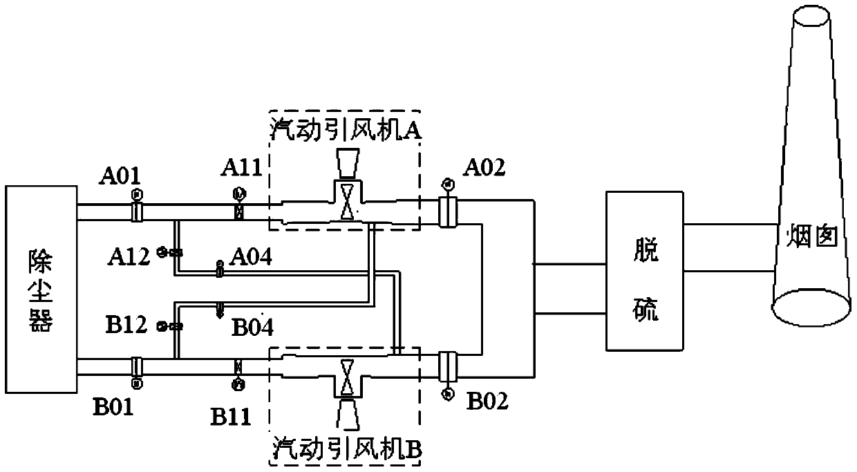
[0048] like Figure 4 Shown is a configuration diagram of a f...


PUM


Abstract

The invention provides a flue gas and air system and a working method of the flue gas and air system. The flue gas and air system comprises a first turbine-driven induced draft fan, a second turbine-driven induced draft fan, a first movable vane or inlet guide vane, a second movable vane or inlet guide vane, a first inlet baffle, a second inlet baffle, a first outlet baffle and a second outlet baffle. A first start-up bypass comprises a first flue and a first valve which is installed on the first flue. A second start-up bypass comprises a second flue and a second valve which is installed on the second flue. The first flue is communicated with an inlet flue of the first turbine-driven induced draft fan, and the second flue is communicated with an inlet flue of the second turbine-driven induced draft fan. According to the invention, due to the fact that the start-up bypasses are added to the inlet flues of the turbine-driven induced draft fans, safe and reliable parallel operation of the induced draft fans can be achieved under the conditions that the construction cost is not remarkably increased, the complexity of the flue gas and air system is not improved, and a large installation space is not required; and when a boiler flameout accident happens, the pumping effect of the turbine-driven induced draft fans on the combustion chamber draft in the idling process can be reduced, and implosion of a combustion chamber can be avoided.

Description

technical field [0001] The invention relates to the technical field of flue gas systems, in particular to a flue gas system and a working method thereof. Background technique [0002] With the increasing capacity of domestic coal-fired power plants, the capacity of boiler induced draft fans also increases. Moreover, the current environmental protection requires that the desulfurization and denitrification system and the induced draft fan unit be put into operation at the same time (the bypass is cancelled), and the combination of the induced draft fan and the desulfurization booster fan has become a new trend, so that the capacity of the induced draft fan is larger. For the induced draft fan driven by the motor, the increase of the motor capacity also brings problems such as an increase in the power consumption rate of the plant, a large starting current, and a need to increase the voltage level of the plant power. [0003] The well-established types of induced draft fans i...

Claims


Application Information

Patent Timeline
Patent Type & Authority Patents(China)
IPC IPC(8): F23L17/00
CPCF23L17/005
Inventor 周江博张清峰李战国张昕解雪涛时道斌
Owner NORTH CHINA ELECTRICAL POWER RES INST
Why Eureka
Try Eureka