
Full-period or half-period synchronous frequency measurement and correction digital demodulation detection system and detection method of amplitude modulation signal

An amplitude modulation signal and digital demodulation technology, applied in the field of digital demodulation, can solve the problems of random error in detection signal measurement results, inability to meet spectral scanning, noise in detection results, etc., to reduce intermediate debugging links, reduce costs, and improve accuracy Effect

Inactive Publication Date: 2017-07-18
JILIN UNIV
View PDF3 Cites 0 Cited by
  • Summary
  • Abstract
  • Description
  • Claims
  • Application Information

AI Technical Summary

Problems solved by technology

[0005] CN102916665A discloses a "two-phase digital lock-in amplifier and its digital domain genlock algorithm", which realizes automatic tracking filtering and genlock functions, and can adapt to input signals with frequency changes, but requires two phases as reference signals The square wave signal with a difference of 90° has the same frequency as the detection signal, and it is necessary to collect three signals and send them to the PC. The phase-locking algorithm is implemented by the PC, which cannot meet the requirements of spectral scanning for real-time sampling.
However, due to the frequency fluctuation of the detection signal itself and the limitation of ADC sampling frequency, it will cause the selection error of the last sampling point of each signal cycle. Although the average of multiple cycles is taken, the measurement results of the detection signal still have random errors, which are manifested as Noise in test results
[0011] It can be seen that the existing digital lock-in amplifiers have detection noise problems for detection signals with unstable frequencies.

Method used


Image

  • Full-period or half-period synchronous frequency measurement and correction digital demodulation detection system and detection method of amplitude modulation signal
  • Full-period or half-period synchronous frequency measurement and correction digital demodulation detection system and detection method of amplitude modulation signal
  • Full-period or half-period synchronous frequency measurement and correction digital demodulation detection system and detection method of amplitude modulation signal

Examples


Embodiment 1

[0044] Amplitude detection for AM signals.

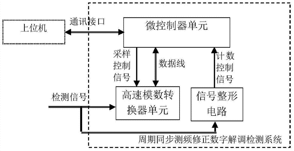
[0045] Such as figure 2 As shown, the full-cycle or half-cycle synchronous frequency measurement correction digital demodulation detection system of the AM signal is composed of a microcontroller unit, a high-speed analog-to-digital converter unit, a signal shaping circuit and an interface. The microcontroller unit is connected to the high-speed analog-to-digital converter unit through the data line and the sampling control signal line, connected to the signal shaping circuit through the counting control signal line, and connected to the host computer through the interface. The detected amplitude modulation signal is respectively connected with the high-speed analog-to-digital converter unit and the signal shaping circuit through the signal interface through the signal line.

[0046] The high-speed analog-to-digital converter unit selects a high-speed analog-to-digital conversion chip, receives the sampling control signal from the...

Embodiment 2

[0067] The light intensity detection of the spectral signal is carried out for the raster scanning spectrometer.

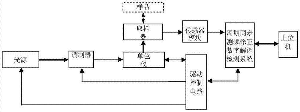
[0068] Such as figure 2 As shown, the raster scanning spectrometer with periodic synchronous frequency measurement and correction digital demodulation is connected with the light source, modulator and monochromator through the drive control circuit by the host computer through the cycle synchronous frequency measurement correction digital demodulation detection control system, and the drive control The circuit is connected with the modulator, and the monochromator is formed by connecting the sampler and the sensor module with the detection system.

[0069] Periodic synchronous frequency measurement correction digital demodulation detection control system such as figure 2 As shown, the microcontroller unit is connected to the high-speed analog-to-digital converter unit through the data line and the sampling control signal line respectively, and is connected to t...


PUM


Abstract

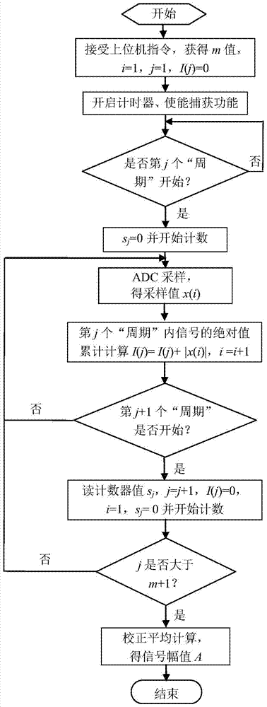
The invention relates to a full-cycle or half-cycle synchronous frequency measurement corrected digital demodulation detection system and detection method of amplitude-modulated signals. The full-cycle or half-cycle synchronous frequency measurement corrected digital demodulation detection system and method can be adopted to realize the amplitude detection of the amplitude-modulated signals. According to the detection system, a micro controller unit is adopted to control a high-speed analog-to-digital conversion unit to perform signal acquisition, and lock-in amplified digital integral and filtering can be realized through absolute value cumulative averaging calculation; and the starting point of a full cycle or a half cycle is captured, and the frequency of the signals is measured through using high-frequency counting, and frequency correction is performed on a detection result. Compared with an existing detection system using a lock-in amplifying circuit, the detection system of the invention has the advantages of simple circuits, no middle debugging process and high detecting precision; compared with an existing simplified digital demodulation detection system, the detection system of the invention can assist in decreasing system detection noise and improving detection accuracy under the premise that the complexity of the circuits and algorithms as well as detection time and cost are not increased.

Description

technical field [0001] The invention relates to a frequency error compensation correction technology for digital demodulation of an amplitude modulation signal detection system, in particular to a digital demodulation method for a signal detection system of a raster scanning spectrometer. Background technique [0002] For the demodulation of the amplitude modulation detection signal, the detection system is usually implemented by a lock-in amplifier circuit: the detection signal and the reference signal (a square wave signal with the same frequency and phase as the measured signal) are subjected to phase-sensitive detection, low-pass filtering, and amplification to obtain The amplitude signal of the same frequency component as the modulating signal, thus effectively suppressing noise and harmonics. Its circuit includes band-pass filtering and amplification of the detection signal, phase shifting of the reference signal, phase-sensitive detection, low-pass filtering and other...

Claims


Application Information

Patent Timeline
Patent Type & Authority Patents(China)
IPC IPC(8): G01J3/433G01J3/02
CPCG01J3/02G01J3/433
Inventor 王智宏季绪飞刘杰王婧茹
Owner JILIN UNIV
Learn More