
Precise delay method for digital detonator

A digital detonator, precise time technology, applied in weapon accessories, fuzes, electric fuzes, etc., can solve problems with high requirements, achieve the effect of improving accuracy and being conducive to widespread application

Inactive Publication Date: 2016-04-20
深圳市中安利业科技技术有限公司
View PDF6 Cites 4 Cited by
  • Summary
  • Abstract
  • Description
  • Claims
  • Application Information

AI Technical Summary

Problems solved by technology

[0004] For the parameter of precise time delay, due to the particularity of the use environment (extremely wide temperature range -45°C to 100°C, strong blasting vibration), the digital detonator can only use internal vibration, and due to voltage changes, and super The requirement of low power consumption can only use ultra-low chip frequency. Under these constraints, the requirements for the MCU of the digital detonator are very high. For many chips, this parameter has become an unbreakable technical bottleneck.

Method used


Image

  • Precise delay method for digital detonator
  • Precise delay method for digital detonator
  • Precise delay method for digital detonator

Examples


Embodiment Construction

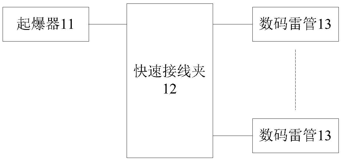
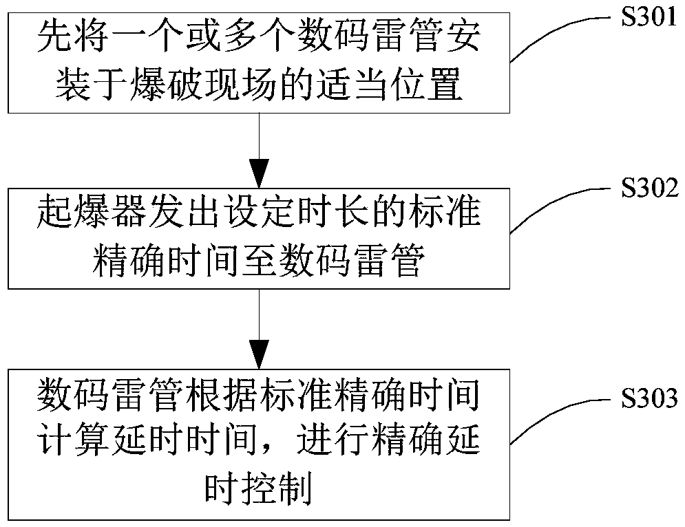
[0027] Such as figure 2 , 3 As shown, in an embodiment of the digital detonator 13 precise delay method of the present invention, it can be used for the precise detonation control of the digital detonator 13, and the standard accurate time sent by the detonator 11 is used as a reference to correct the internal vibration of the digital detonator 13 The error range, thereby calculating the precise delay time, greatly improves the accuracy, so that the MCU and single-chip microcomputer with a large internal vibration error range can be used to make the digital detonator 13, which breaks through the limitation of the time accuracy of the existing technology and is beneficial to the digital detonator. Wide application of detonator 13.

[0028] Such as figure 2 As shown, in this embodiment, the digital detonator 13 can be one or more, including MCU, ignition switch, igniter, power supply, etc., and can be connected with the detonator 11 (centralized controller) through the quick...


PUM


Abstract

The invention relates to a precise delay method for a digital detonator. The precise delay method comprises the following steps: S1: mounting the digital detonator at an explosion site, and electrically connecting the digital detonator to an exploder; S2: sending standard precise time with designed time length to the digital detonator by virtue of the exploder; and S3: calculating delay time according to standard precise time by virtue of the digital detonator. According to the precise delay method, by taking the standard precise time sent by the exploder as reference, an error range of internal vibration of the digital detonator is corrected, so that the precise delay time is calculated, and the precision is greatly improved, and therefore, an MCU, a single chip microcomputer and the like with relatively great internal vibration error range can be used for manufacturing the digital detonator, the limitation, related to time precision, of the prior art is broken through, and wide popularization and application of the digital detonator is facilitated.

Description

technical field [0001] The invention relates to the detonation technology of a detonator, and more specifically relates to a precise time-delay method for a digital detonator. Background technique [0002] With the development of economy and society, engineering blasting counting has been more and more widely used. In some occasions that require relatively high blasting, such as mines, tunnels, buildings, etc., the method of multi-stage detonation with small equivalent is often used. Multi-stage detonation requires precise control of the delay time, and the expected blasting effect cannot be obtained if the delay time is too long or too short. [0003] Such as figure 1 As shown, it is a schematic diagram of the principle of a digital detonator in the prior art. The digital detonator is connected to the detonator 1 through the power supply and the communication interface, and is connected to the power supply and the detonation signal; the MCU2 of the digital detonator contr...

Claims


Application Information

Patent Timeline
Patent Type & Authority Applications(China)
IPC IPC(8): F42C19/12F42C11/06
CPCF42C19/12F42C11/06
Inventor 余静宁洪铭杰刘华唐彬
Owner 深圳市中安利业科技技术有限公司
Learn More