Method for calibrating central point of robot tool through employing plane calibration plate

A tool center point and calibration method technology, which is applied in the field of robot tool center point calibration, can solve the problems of low precision and complicated calibration operation, and achieve the effect of automatic control, high calibration accuracy and simple operation

Inactive Publication Date: 2016-04-20
CENT SOUTH UNIV
View PDF7 Cites 18 Cited by
  • Summary
  • Abstract
  • Description
  • Claims
  • Application Information

AI Technical Summary

Problems solved by technology

[0010] The present invention proposes a method for calibrating the center point of a robot tool using a plane calibration board, the purpose of which is to overcome the problems of complex calibration operations and low precision in the prior art, and to assist the robot TCP by using a calibration board with high plane precision. Calibration work, reducing the difficulty of alignment during the calibration process, improving calibration efficiency, easy to achieve calibration automation, and reducing costs

Method used


Image

  • Method for calibrating central point of robot tool through employing plane calibration plate
  • Method for calibrating central point of robot tool through employing plane calibration plate
  • Method for calibrating central point of robot tool through employing plane calibration plate

Examples


Embodiment Construction

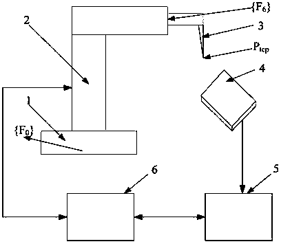
[0024] see figure 1 , {F 0} is the robot world coordinate system established in the space where the robot base is located, {F 6} is the coordinate system of the robot end flange fixed on the end flange of the robot. The computer 5 is used to collect the contact sensor signal of the calibration plate to determine whether the calibration plate is touched. The computer is connected to the robot controller 6 through the network. When the touch signal appears on the calibration board, it can send a stop motion signal to the robot, and the computer simultaneously reads the robot corner joint information from the robot controller and completes subsequent calculations.

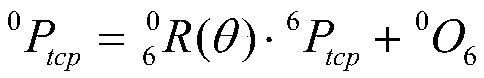
[0025] P tcp Set as the target setting point of TCP, the core of the calibration work is to find out the point at {F 6} coordinates in 6 P tcp ={ 6 x tcp , 6 the y tcp , 6 z tcp} T . The point is in the robot world coordinate system {F 0} coordinates are 0 P tcp ={ 0 x tcp , 0 the y tcp , 0 z tcp} ...


PUM


Abstract

The invention discloses a method for calibrating a central point of a robot tool through employing a plane calibration plate. The method comprises the steps: controlling a robot to enable a TCP to carry out plane contact with a calibrating tool for more than six times at different attitudes during calibration; just recording the coordinate information of a robot joint; combing with the structure parameter of the robot to calculate the coordinates of the TCP in a flange coordinate system at the tail end of the robot; and evaluating the calibration precision. The method does not need to enable the TCP of the robot to repeatedly coincide with the same fixed point, and lowers the point-point coincidence to the point-plane coincidence. A calibration tool is simple, and the method is easy to implement. When the TCP of the robot deflects lightly, the method can achieve autonomous calibration.

Description

technical field [0001] The invention relates to a robot tool center point (Tool center point, TCP) calibration method, in particular to a robot tool center point calibration method using a plane calibration plate. Background technique [0002] The robot tool center point (Toolcenterpoint, TCP) is the origin of the tool coordinate system fixedly connected with the robot tool, and the coordinates of the actual working point of the tool in the tool coordinate system remain unchanged. In order for the robot to accurately control the position of the actual working point of the tool, it must first obtain the origin of the tool coordinate system, that is, the coordinates of the TCP in the flange coordinate system at the end of the robot. [0003] The process of calculating the coordinates of the TCP in the robot end flange coordinate system is called robot tool center point calibration. Accurate calibration of robot TCP is the basis for off-line programming. [0004] The core of ...

Claims


Application Information

Patent Timeline
Patent Type & Authority Applications(China)
IPC IPC(8): G01B21/00
CPCG01B21/00
Inventor 韩奉林江晓磊严宏志何锐波
Owner CENT SOUTH UNIV
Why Eureka
Try Eureka