Bandpass filtering type multifunctional power tester based on voltage comparison circuit

A technology of voltage comparison circuit and band-pass filter, which is applied in the direction of electric power measurement through current/voltage, measurement of current/voltage, and components of electrical measuring instruments, etc., which can solve problems such as single function, avoid misjudgment, and have high precision , The effect of improving test efficiency

Inactive Publication Date: 2016-04-20
CHENGDU HONGKAIRUI TECH CO LTD
View PDF12 Cites 2 Cited by
  • Summary
  • Abstract
  • Description
  • Claims
  • Application Information

AI Technical Summary

Problems solved by technology

[0003] The purpose of the present invention is to overcome the defect of the single function of the existing power tester and provide a band-pass filter multifunctional power tester based on the voltage comparison circuit

Method used


Image

  • Bandpass filtering type multifunctional power tester based on voltage comparison circuit
  • Bandpass filtering type multifunctional power tester based on voltage comparison circuit
  • Bandpass filtering type multifunctional power tester based on voltage comparison circuit

Examples


Embodiment

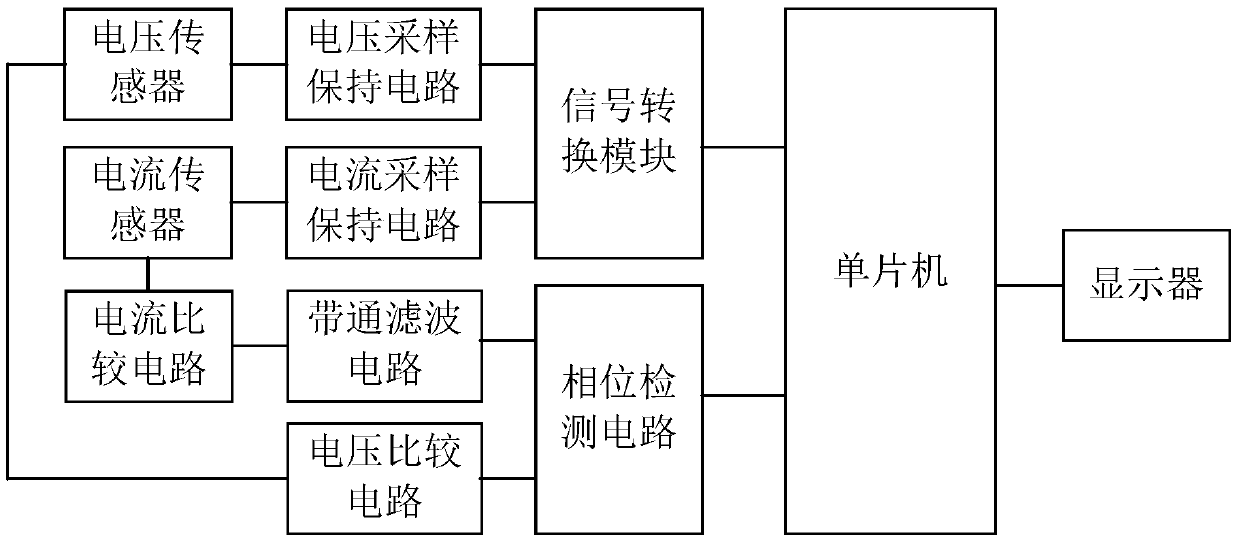
[0023] Such as figure 1 Shown, a kind of band-pass filter type multifunction power tester based on the voltage comparator circuit of the present invention mainly consists of a single-chip microcomputer, a voltage sensor, a current sensor, a signal conversion module connected to the single-chip microcomputer, a phase detection circuit and a display, respectively A voltage sampling and holding circuit and a current sampling and holding circuit connected to the signal conversion module, a current comparison circuit and a voltage comparison circuit respectively connected to the phase detection circuit, and a belt connected in series between the current comparison circuit and the phase detection circuit The voltage sensor is connected in series between the voltage sampling and holding circuit and the voltage comparison circuit; the current sensor is connected in series between the current sampling and holding circuit and the current comparison circuit.

[0024] Wherein, single-chip...


PUM


Abstract

The invention discloses a bandpass filtering type multifunctional power tester based on a voltage comparison circuit. The bandpass filtering type multifunctional power tester is mainly composed of a single-chip microcomputer, a voltage transducer and a current transducer. The power tester is further composed of a signal conversion module, a phase detection circuit and a display which are respectively connected with the single-chip microcomputer, a voltage sampling maintaining circuit and a current sampling maintaining circuit which are respectively connected with the signal conversion module, a current comparison circuit and the voltage comparison circuit which are respectively connected with the phase detection circuit, and a bandpass filtering circuit which is connected in series between the current comparison circuit and the phase detection circuit. The bandpass filtering type multifunctional power tester provided by the invention can simultaneously test voltages, currents and power parameter signals of equipment, and enables test personnel to more comprehensively understand the operation condition of the equipment. The voltage comparison circuit can convert voltage signals acquired by the voltage transducer into corresponding square wave signals, the conversion efficiency is high, and the test efficiency is improved accordingly.

Description

technical field [0001] The invention relates to a power tester, in particular to a band-pass filter multifunctional power tester based on a voltage comparison circuit. Background technique [0002] At present, the power tester has been widely used in the online detection and maintenance of industrial equipment. However, the traditional power tester has a single function, which is limited to detecting the power of the equipment, but cannot detect the key operating parameters such as the operating voltage and current of the equipment, so it cannot fully reflect the operation of the equipment. Contents of the invention [0003] The purpose of the present invention is to overcome the defect of single function of the existing power tester, and provide a band-pass filter multifunctional power tester based on a voltage comparison circuit. [0004] The purpose of the present invention is achieved through the following technical solutions: a band-pass filter multifunctional power ...

Claims


Application Information

Patent Timeline
Patent Type & Authority Applications(China)
IPC IPC(8): G01R21/06G01R19/00G01R1/30
CPCG01R1/30G01R19/00G01R21/06
Inventor 韩群艳
Owner CHENGDU HONGKAIRUI TECH CO LTD
Why Eureka
Try Eureka