Radio frequency cable fault positioning detection device and method

A radio frequency cable and fault location technology, which is applied to the fault location and uses the pulse reflection method to detect faults. It can solve the problems of low measurement efficiency, limited measurement distance, and inability to realize cable fault location detection. The effect of improving the measurement distance and improving the test efficiency

Inactive Publication Date: 2016-04-20
THE 41ST INST OF CHINA ELECTRONICS TECH GRP
View PDF7 Cites 18 Cited by
  • Summary
  • Abstract
  • Description
  • Claims
  • Application Information

AI Technical Summary

Problems solved by technology

[0004] However, this method requires calibration and error correction operations when measuring RF cables, and the measurement efficiency is low. When the ambient temperature changes greatly, the calibration data will become invalid, and the calibration operation must be performed again, and the RF cables cannot be monitored in real time; and the measurement distance Due to the limitation of the directivity index of the measuring instrument, it is impossible to realize the fault location detection of the long-distance cable

Method used


Image

  • Radio frequency cable fault positioning detection device and method
  • Radio frequency cable fault positioning detection device and method
  • Radio frequency cable fault positioning detection device and method

Examples


Embodiment Construction

[0034] Below in conjunction with accompanying drawing and specific embodiment the present invention is described in further detail:

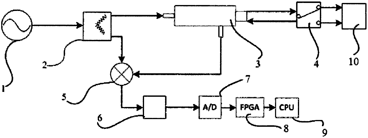
[0035] In the present invention, the radio frequency cable fault location detection device, such as figure 1 As shown, it includes excitation source 1, power divider 2, directional coupler 3, measurement port 4, mixer 5, filter amplification module 6, A / D conversion module 7, FPGA processor 8 and CPU9, where:

[0036] An excitation source 1 is used to generate a linear frequency sweep signal and transmit the linear frequency sweep signal to a power divider 2;

[0037] The power divider 2 is used to receive the linear frequency sweep signal from the excitation source, and transmit the linear frequency sweep signal to the directional coupler 3 and the mixer 5 respectively;

[0038] The directional coupler 3 is used to receive the linear sweep signal sent by the power divider 2, and transmit the signal to the measurement port 4; simultaneously rec...


PUM


Abstract

The invention relates to a radio frequency cable fault positioning detection device and method. The device comprises an excitation source for generating a sweep frequency signal, a power divider for enabling a signal to be transmitted to a directional coupler and a frequency mixer, the directional coupler which is used for receiving the signal, enabling the signal to be transmitted to a measurement port, receiving a reflection signal transmitted by the measurement port, and transmitting the signal to the frequency mixer, the measurement port which is used for enabling the received signal to be outputted to a measured radio frequency cable, receiving the reflection signal, and transmitting the reflection signal to the directional coupler, the frequency mixer which is used for enabling the sweep frequency signal and the reflection signal to be mixed to obtain a difference frequency signal, and transmitting the difference signal to a filter amplification module, the filter amplification module, an A/D conversion module, an FPGA processor, and a CPU which is used for carrying out Fourier transform so as to obtain a difference frequency signal frequency value and a power value. The method does not need correction, is high in testing efficiency, can achieve real-time monitoring, is large in measurement distance, and is low in installation and maintenance cost.

Description

technical field [0001] The invention relates to the technical field of cable fault detection, in particular to a radio frequency cable fault location detection device and a detection method thereof. Background technique [0002] Radio frequency cables are indispensable components in radio communication systems and electronic equipment, and have been widely used in wireless communication and broadcasting, television, radar, navigation, computers and instruments, so the detection and maintenance of radio frequency cables is very important. In order to accurately and timely detect cable faults and reduce losses caused by communication cable faults, more and more communication systems require real-time fault monitoring of radio frequency cables. [0003] The existing most widely used cable fault location and detection instrument is based on the principle of frequency domain reflection and the design of a single-port vector network analyzer. It consists of an excitation signal so...

Claims


Application Information

Patent Timeline
Patent Type & Authority Applications(China)
IPC IPC(8): G01R31/08G01R31/11
Inventor 祝林林朱伟张晓来王凯孙林郑恢康
Owner THE 41ST INST OF CHINA ELECTRONICS TECH GRP
Why Eureka
Try Eureka