
Deposition method of silicon oxide thin film and preparation method of low temperature polycrystalline silicon TFT substrate

A technology of low-temperature polysilicon and deposition method, applied in transistors, semiconductor/solid-state device manufacturing, semiconductor devices, etc., can solve problems such as flat-band voltage drift, many interface defects, surface damage, etc., and achieve TFT electrical properties improvement, TFT electrical properties Good, improve the effect of film quality

Active Publication Date: 2016-04-20
CHANGSHA HKC OPTOELECTRONICS CO LTD
View PDF4 Cites 7 Cited by
  • Summary
  • Abstract
  • Description
  • Claims
  • Application Information

AI Technical Summary

Problems solved by technology

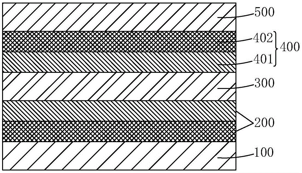
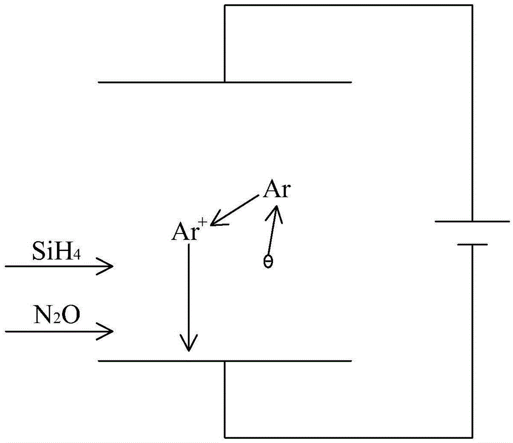
[0007] The commonly used method for depositing silicon oxide films is plasma enhanced chemical vapor deposition (PlasmaEnhancedChemicalVaporDeposition, PECVD), such as figure 2 Shown, the existing plasma-enhanced chemical vapor deposition method of silicon oxide thin film is: feed argon (Ar) in the chemical vapor deposition device, produce argon ion (Ar) in the radio frequency environment of 13.5MHz or 27.12MHz + ), using Ar + As an ion source, the reaction gas SiH is bombarded under the action of an electric field 4 with N 2 O makes the reaction gas activated by bombardment, and then a chemical reaction occurs on the surface of the substrate (such as the polysilicon layer 300 of the low-temperature polysilicon TFT substrate) to generate silicon oxide. The reaction formula of this chemical reaction is: SiH 4 +N 2 O→SiO x +N 2 +H 2 O, where N 2 The nitrogen component in O makes the interface defects between the silicon oxide film 401 and the polysilicon layer 300 produced are more, resulting in a large flat-band voltage drift; secondly, Ar in the PECVD process + As a plasma source hits the surface of the silicon oxide film 401, it is easy to form interface defects and surface damage

Method used


Image

  • Deposition method of silicon oxide thin film and preparation method of low temperature polycrystalline silicon TFT substrate
  • Deposition method of silicon oxide thin film and preparation method of low temperature polycrystalline silicon TFT substrate
  • Deposition method of silicon oxide thin film and preparation method of low temperature polycrystalline silicon TFT substrate

Examples


Embodiment Construction

[0045] In order to further illustrate the technical means adopted by the present invention and its effects, the following describes in detail in conjunction with preferred embodiments of the present invention and accompanying drawings.

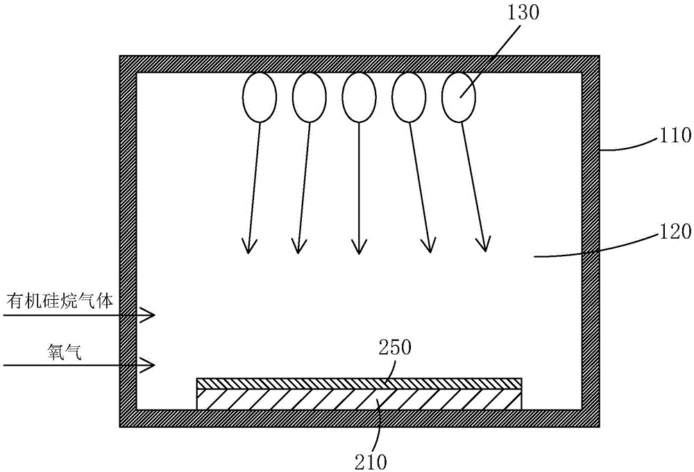
[0046] see image 3 , the invention provides a method for depositing a silicon oxide film, comprising the steps of:

[0047] Step 1. A chemical vapor deposition device 110 is provided. The chemical vapor deposition device 110 has a reaction chamber 120 , and an ultraviolet light source 130 is arranged above the reaction chamber 120 .

[0048] Step 2, placing a substrate 210 at the bottom of the reaction chamber 120, passing organosilane gas and oxygen into the reaction chamber 120, turning on the ultraviolet light source 130, and the oxygen decomposes under the irradiation of ultraviolet light Free oxygen is generated, and the organic silane gas reacts with free oxygen to form silicon oxide (SiO x ), deposited on the substrate 210 to form a ...


PUM

PropertyMeasurementUnit
wavelengthaaaaaaaaaa

Abstract

The invention provides a deposition method of a silicon oxide thin film and a preparation method of a low temperature polycrystalline silicon TFT substrate. According to the deposition method of the silicon oxide thin film, ultraviolet light is introduced as auxiliary energy for a silicon oxide deposition reaction, oxygen is decomposed into free oxygen through the ultraviolet light, the ultraviolet light reacts with organosilane gas to generate silicon oxide, thereby the silicon oxide is deposited in an environment without plasmas for forming the silicon oxide thin film, interface defects and surface damage caused due to the fact that the surface of the silicon oxide thin film is impacted by the high energy plasmas are avoided, and film forming quality of the silicon oxide thin film is improved. According to the preparation method of the low temperature polycrystalline silicon TFT substrate, the silicon oxide thin film in a gate electrode insulating layer is fabricated through the method that the organosilane gas reacts with the oxygen to generate the silicon oxide in the environment with ultraviolet irradiation, surface defects and interface damage caused by plasmas to the surface of the silicon oxide thin film in the current plasma reinforced chemical vapor deposition method are avoided, thereby film forming quality of the silicon oxide thin film is improved, and the electrical property of a TFT is enhanced.

Description

technical field [0001] The invention relates to the field of display technology, in particular to a method for depositing a silicon oxide film and a method for preparing a low-temperature polysilicon TFT substrate. Background technique [0002] With the development of display technology, liquid crystal displays (Liquid Crystal Display, LCD) and other flat display devices are widely used in mobile phones, TVs, personal digital assistants due to their advantages of high image quality, power saving, thin body and wide application range. , digital cameras, notebook computers, desktop computers and other consumer electronics products have become the mainstream of display devices. [0003] Most of the liquid crystal display devices currently on the market are backlight liquid crystal displays, which include a liquid crystal display panel and a backlight module. The working principle of the liquid crystal display panel is to place liquid crystal molecules between two parallel glas...

Claims


Application Information

Patent Timeline
Patent Type & Authority Applications(China)
IPC IPC(8): H01L21/314H01L29/786H01L27/12
CPCH01L21/02214H01L21/02271H01L21/0231H01L27/1214H01L29/78672H01L29/4908H01L21/02164H01L21/02216H01L21/02277H01L21/67115H01L29/66757H01L27/12H01L21/763H01L29/78675
Inventor 马伟欣
Owner CHANGSHA HKC OPTOELECTRONICS CO LTD
Learn More