Mobile terminal with metal shell and antenna structure thereof

A technology for metal shells and mobile terminals, applied in the connection of antenna grounding switch structures, antenna equipment with additional functions, antennas, etc., to achieve the effects of simplifying the structure, reducing costs, and reducing losses

Active Publication Date: 2016-04-20
SHENZHEN SUNWAY COMM
View PDF7 Cites 13 Cited by
  • Summary
  • Abstract
  • Description
  • Claims
  • Application Information

AI Technical Summary

Problems solved by technology

[0006] The antenna structure of the above-mentioned patent application still cannot

Method used


Image

  • Mobile terminal with metal shell and antenna structure thereof
  • Mobile terminal with metal shell and antenna structure thereof
  • Mobile terminal with metal shell and antenna structure thereof

Examples


Embodiment 1

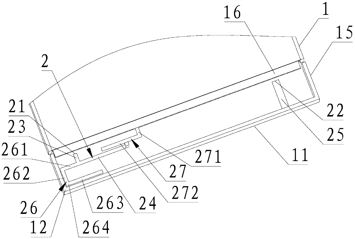
[0055] Please refer to figure 1 with image 3 , providing an antenna structure for a mobile terminal with a metal casing, the antenna structure is a loop antenna, applicable to mobile phones, tablets, MP3 players or other mobile terminal communication devices, and the mobile communication terminal includes a full metal casing and a main antenna 2. A PCB main board is arranged inside the all-metal shell, and a clearance area is provided above the PCB main board, and a main antenna 2 is arranged in the clearance area;

[0056] A metal frame 11 extending from the back of the mobile terminal communication device to the side is provided at the edge of the all-metal casing, and the metal casing 1 will serve as a part of the antenna structure to increase the frequency band coverage of the antenna.

[0057] The main antenna 2 includes a first feed point 21, a first return point 22, a first short feed branch 23, a second long feed branch 24, and a first return ground branch 25; The f...

Embodiment 2

[0066] Please refer to figure 1 , this embodiment is a further extension on the basis of Embodiment 1, specifically including:

[0067] The main antenna 2 also includes a parasitic branch 27, one end of which is connected to the metal casing, preferably directly connected to the metal frame 11; Preferably, the parasitic branch 27 is L-shaped, the L-shaped short arm 271 is directly connected to a metal frame 11 of the metal casing, and the L-shaped long arm 272 is connected to the second feed long branch 24 parallel to the length direction.

[0068] The role of the parasitic branch 27 is to adjust the impedance of the entire high frequency band, make the impedance closer to match, and adjust the low frequency bandwidth and impedance; adjusting the impedance means adjusting the frequency and the return loss of the antenna at the same time.

[0069] It should be noted that the parasitic branch 27 is added in this embodiment, and the high-frequency bandwidth can be greatly incre...

Embodiment 3

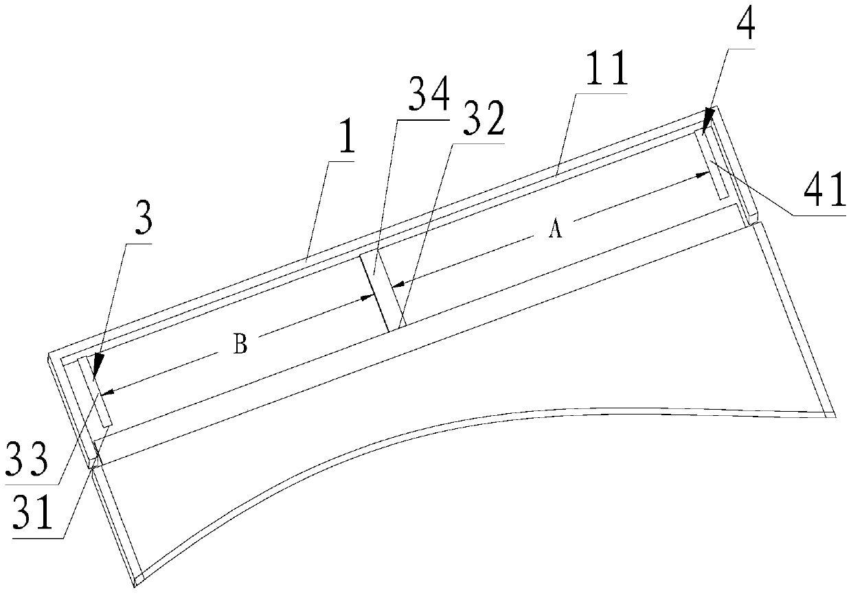
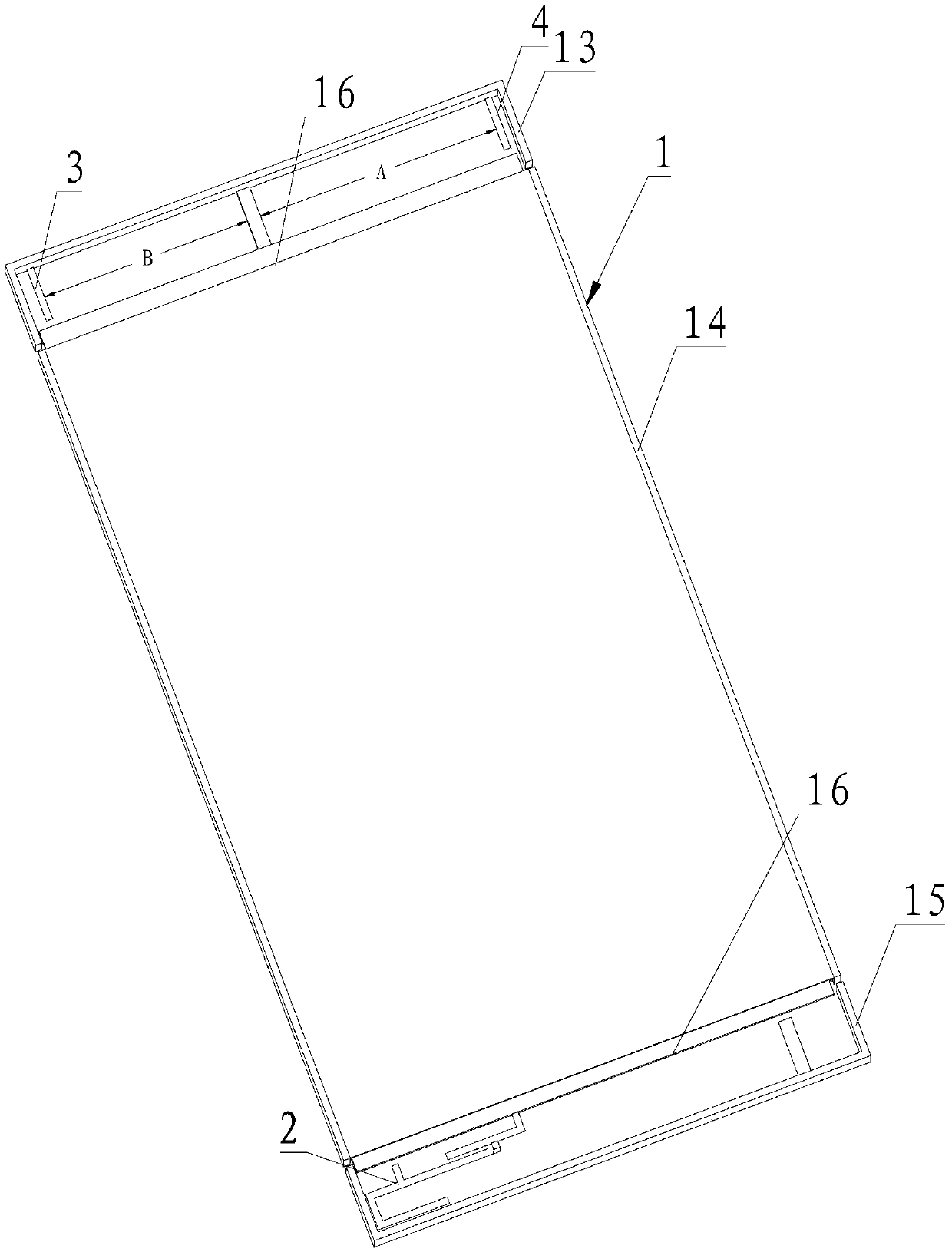
[0071] see Figure 1-Figure 3 , this embodiment combines Embodiment 1 and Embodiment 2, and is further extended to add a diversity antenna 3 and a GPS / WLAN antenna 4 . Specifically:

[0072] The metal casing is separated in sections along the length direction, and is successively divided into a first metal casing 13, a second metal casing 14 and a third metal casing 15; the first metal casing 13, the second metal casing 14 and the third metal casing A gap 16 communicating with the outside world is provided between the shells 15 to ensure normal transmission and reception of antenna signals;

[0073] The diversity antenna 3 and the GPS / WLAN antenna 4 are located in the first metal housing 13; the main antenna 2 is located in the third metal housing 15; the first metal housing 13 is preferably located on the top of the back cover of the mobile terminal communication device; The third metal shell 15 is located at the bottom of the back cover;

[0074] The diversity antenna 3 i...


PUM


Abstract

The invention provides an antenna structure of a mobile terminal with a metal shell. The antenna structure comprises a main antenna, the metal shell and a tuning switch; the main antenna comprises a first feeding point, a first earth point, a first feeding short branch, a second feeding long branch and a first earth branch; one end of the first feeding short branch is connected with the first feeding point, and the other end of the first feeding short branch is connected with one end of the second feeding long branch; the other end of the second feeding long branch is connected with the metal shell; one end of the first earth branch is connected with the first earth point through the tuning switch, and the other end of the first earth branch is connected with the metal shell. According to the mobile terminal with the metal shell and the antenna structure thereof, the main antenna can provide a low-frequency bandwidth ranging from 880 MHz to 960 MHz and a high-frequency bandwidth ranging from 1,710 MHz to 2,690 MHz; a low-frequency resonance can be switched through the tuning switch arranged on the earth end of the main antenna, expanding of the low-frequency bandwidth is achieved, and it is guaranteed that the range of the working frequency applied to the antenna with the metal shell reaches the coverage area of an LTE frequency band of 4G.

Description

technical field [0001] The invention relates to the antenna field of communication equipment, in particular to a mobile terminal with a metal casing and an antenna structure thereof. Background technique [0002] The issuance of the fourth-generation mobile communication license based on the core technology LTE (LONGTER MEVOLUTION) means that my country's mobile communication industry has entered the 4G era. 4G LTE technology has a minimum low frequency requirement of 880MHz-960MHz for antenna bandwidth, and a minimum high frequency requirement of 1710MHz-2690MHz. For mobile phones, another frequency band has been added. How to achieve multi-band coverage without increasing the complexity of the antenna has become one of the focuses of the industry. [0003] At the same time, the integration of the metal frame is ensured by adopting CNC numerical control machine tools and so on. Metal frames and metal shells gradually appear in mobile phone products, and the introduction o...

Claims


Application Information

Patent Timeline
IPC IPC(8): H01Q1/36H01Q1/44H01Q1/48H01Q1/50H01Q5/10H01Q5/20H01Q5/28H01Q5/314H01Q5/371H01Q5/378H01Q21/00
CPCH01Q1/36H01Q1/44H01Q1/48H01Q1/50H01Q21/00
Inventor 李开亮谷媛尹鸿焰
Owner SHENZHEN SUNWAY COMM
Why Eureka
Try Eureka