
Fin-style vehicular antenna and method for producing same

A vehicle-mounted antenna and fin-type technology, applied in the field of signal receiving devices, can solve problems such as performance failure, separation of two parts, and inability to effectively use space, and achieve the effects of convenient processes, ensuring receiving performance, and effectively using space.

Inactive Publication Date: 2016-04-20
JIANGSU HUASHENG AUTOMOTIVE ELECTRONICS CO LTD
View PDF8 Cites 5 Cited by
  • Summary
  • Abstract
  • Description
  • Claims
  • Application Information

AI Technical Summary

Problems solved by technology

However, because the shark fin car antenna in the prior art is usually placed inside the antenna casing, the space cannot be used effectively, and it may be restricted by the casing, so it cannot effectively achieve the antenna design receiving gain
However, if the antenna is separated from the housing, it is easy to cause the two parts to be separated during subsequent use and the performance will fail.

Method used


Image

  • Fin-style vehicular antenna and method for producing same

Examples


Embodiment 1

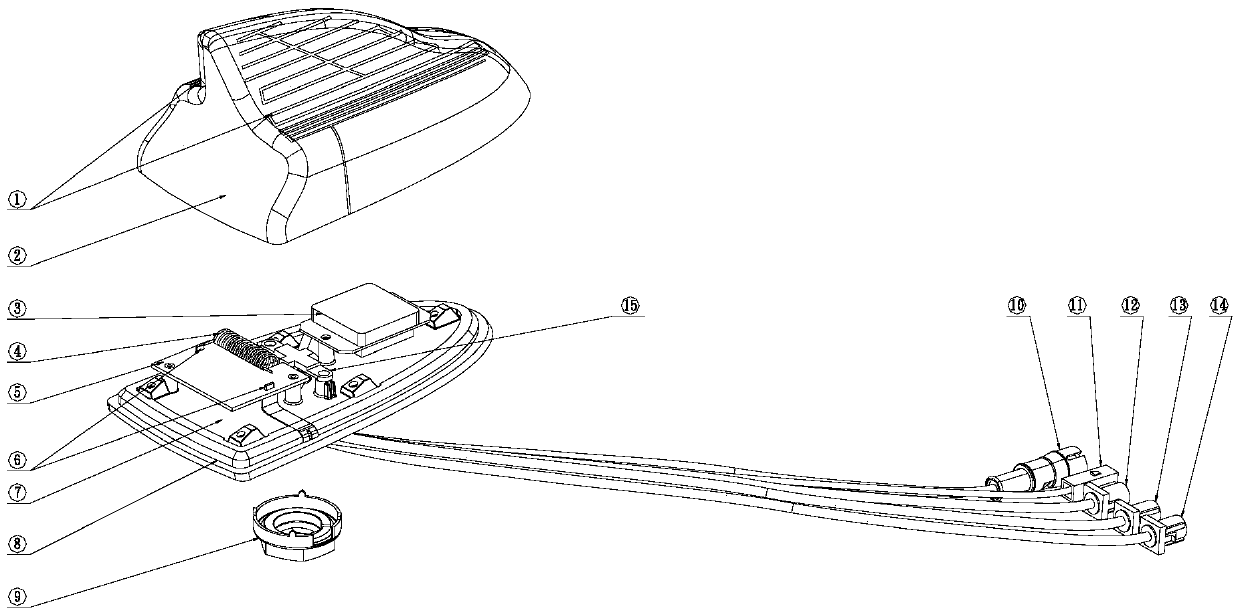
[0027] Such as figure 1 As shown, a fin-type vehicle-mounted antenna according to the present invention includes an upper cover 2 and a base 7, and the upper cover 2 and the base 7 are connected to form a closed accommodating space, and the accommodating space is provided with There are connecting elements 6, antenna amplifiers 5 for low-noise amplification of received electric wave signals, tuning elements 4 for adjusting the received self-resonance parameters of the antennas, GPS antennas 3 for navigation and positioning, and a plurality of antennas for communicating with A connector for external connection, wherein the connection element 6 is electrically connected to the antenna amplifier 5 and the tuning element 4 respectively, the connection element 6, the antenna amplifier 5, the tuning element 4, the GPS antenna 3 are all arranged on the base 7.

[0028] The outer surface of the upper cover 2 is provided with a receiving antenna 1 for receiving radio signals of variou...

Embodiment 2

[0038] A preparation method based on the fin type vehicular antenna described in embodiment 1, comprises the steps:

[0039] S1: Synthesize a modified plastic raw material containing LDS laser powder, and inject or die-cast it into a plastic part, which is the upper cover.

[0040] S2: Scan the plastic part through laser activation technology to form a metal pattern that restores metal particles. Preferably, it activates the Sanlaser laser powder by means of a laser.

[0041] S3: Electroless plating is carried out on the plastic part with the metal pattern to thicken the technical layer on the metal pattern to form a continuous conductive pattern.

[0042] The working principle of this embodiment is: when preparing the antenna upper cover material, on the basis of using the original plastic material, an organic metal complex and a laser additive are added (this additive is suitable for adding thermoplastics, because the organic metal complex and the laser additive It is a co...


PUM


Abstract

The invention discloses a fin-style vehicular antenna and a method for producing the same. The fin-style vehicular antenna comprises a top cover and a base which are connected to form an enclosed receiving space. A connection element, an antenna amplifier, a tuning element, a GPS antenna, and multiple socket connectors are disposed in the receiving space. A receiving antenna is disposed on the outer surface of the top cover. The feed line of the receiving antenna is connected with the antenna amplifier through the connection element and the tuning element. The top cover is prepared from a modified plastic material containing LDS laser powders. After the top cover is formed, three-dimensional layout is easily achieved by means of LDS (laser direct structuring) technology and convenient processes according to a designed antenna pattern. Injection molding is carried out by using laser inducing material and selective metallization is carried out after laser activation in order that a high-precision circuit intersection structure is formed. The receiving performance of the antenna is guaranteed and space is effectively utilized.

Description

technical field [0001] The invention relates to the technical field of signal receiving devices, in particular to a fin-type vehicle-mounted antenna and a preparation method thereof. Background technique [0002] Shark fin car antenna products apply the world's leading electronic technology. Compared with traditional telescopic antennas, whip antennas and car glass antennas, shark fin car antennas integrate various powerful car electronic functions such as FM, GPS, and GSM, and Effectively integrate "fashion" and "functionality" to achieve perfection. However, because the shark fin car antenna in the prior art is usually placed inside the antenna casing, the space cannot be effectively used, and it may be restricted by the casing, so that the receiving gain of the antenna design cannot be effectively achieved. However, if the antenna is separated from the housing, the two parts are likely to be separated during subsequent use and the performance will fail. [0003] Therefo...

Claims


Application Information

Patent Timeline
IPC IPC(8): H01Q1/42H01Q1/38
CPCH01Q1/42H01Q1/38
Inventor 张学磊段恩敏
Owner JIANGSU HUASHENG AUTOMOTIVE ELECTRONICS CO LTD
Learn More