A distribution cabinet

A technology for power distribution cabinets and cabinet doors, which is applied to substation/power distribution device casings, electrical components, substation/switch layout details, etc., which can solve problems such as inconvenient opening of cabinet doors and poor heat dissipation of power distribution cabinets, and achieve Easy installation and movement, convenient cabinet door, and extended service life

Active Publication Date: 2017-09-26
JIANGSU ZHONGHAI HEAVY MACHINE TOOL
View PDF2 Cites 2 Cited by
  • Summary
  • Abstract
  • Description
  • Claims
  • Application Information

AI Technical Summary

Problems solved by technology

[0005] In order to overcome the problem in the prior art that it is inconvenient to open the cabinet door during maintenance and the problem of poor heat dissipation of the power distribution cabinet in the prior art, the present invention provides a power distribution cabinet with good heat dissipation performance and convenient maintenance

Method used


Image

  • A distribution cabinet
  • A distribution cabinet
  • A distribution cabinet

Examples


Embodiment 1

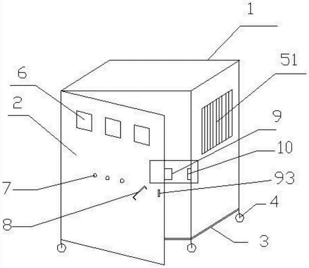
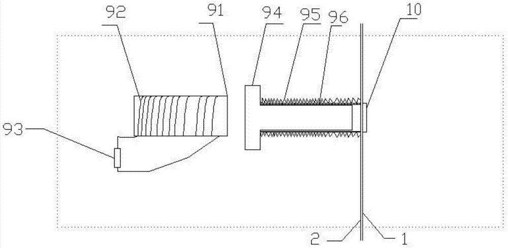
[0032] Such as figure 1 As shown, a power distribution cabinet includes a cabinet body 1, a cabinet door 2, and a base 3. The cabinet door 2 is connected to the cabinet body 1 through a rotating shaft type movable hinge; the base 3 has four legs, and rollers 4 are installed on the legs; The upper part of the door 2 is provided with a square window 6 for installing display instruments; the cabinet door 2 is provided with a circular through hole 7 for installing control buttons; the cabinet door 2 is equipped with a handle 8 made of insulating material; the cabinet door 2 The opening angle is greater than 120°, and the inner wall of the cabinet door 2 is also provided with an installation box near the edge of the cabinet door, and a push-type soft magnetic switch 9 is arranged in the box. Such as figure 2 As shown, the push-type soft magnetic switch 9 includes: a soft magnetic core 91, an insulating coil 92, a button 93 for controlling the current on and off of the coil, an ir...

Embodiment 2

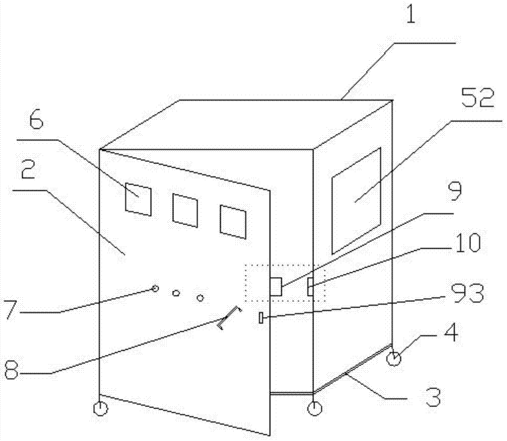
[0036] Such as image 3As shown, a power distribution cabinet includes a cabinet body 1, a cabinet door 2, and a base 3. The cabinet door 2 is connected to the cabinet body 1 through a rotating shaft type movable hinge; the base 3 has four legs, and rollers 4 are installed on the legs; The upper part of the door 2 is provided with a square window 6 for installing display instruments; the cabinet door 2 is provided with a circular through hole 7 for installing control buttons; the cabinet door 2 is equipped with a handle 8 made of insulating material; the cabinet door 2 The opening angle is greater than 120°, and the inner wall of the cabinet door 2 is also provided with an installation box near the edge of the cabinet door, and a push-type soft magnetic switch 9 is arranged in the box. The push-type soft magnetic switch 9 includes: a soft magnetic core 91, an insulating coil 92, a button 93 for controlling the current on and off of the coil, an iron bolt 94 for locking the cab...

Embodiment 3

[0039] refer to figure 2 As shown, a power distribution cabinet includes a cabinet body 1, a cabinet door 2, and a base 3. The cabinet door 2 is connected to the cabinet body 1 through a rotating shaft type movable hinge; the base 3 has four legs, and rollers 4 are installed on the legs; The upper part of the door 2 is provided with a square window 6 for installing display instruments; the cabinet door 2 is provided with a circular through hole 7 for installing control buttons; the cabinet door 2 is equipped with a handle 8 made of insulating material; the cabinet door 2 The opening angle is greater than 120°, and the inner wall of the cabinet door 2 is also provided with an installation box near the edge of the cabinet door, and a push-type soft magnetic switch 9 is arranged in the box. The structures and functions of other components are the same as in Embodiment 2.

[0040] Cabinet body 1 has heat radiation window 52 except three sides of cabinet door, and metal filter sc...


PUM


Abstract

The invention provides a power distribution cabinet which comprises a cabinet body, a cabinet door and a base. The cabinet door and the cabinet body are connected through a rotating shaft type movable hinge. Four supporting legs are arranged on the base and provided with four wheels. A square window is formed in the upper portion of the cabinet door and used for installing a display instrument. A circular through hole is formed in the cabinet door and used for installing a control button. A handle made of insulating material is arranged on the cabinet door and used for pushing and pulling the cabinet door. The power distribution cabinet is characterized in that the opening angle of the cabinet door is larger than 120 degrees, the position, close to the edge of the cabinet door, of the inner wall of the cabinet door is provided with an installation box, and a pressing type soft magnetic switch is arranged in the installation box. The power distribution cabinet is convenient to overhaul; due to the cooling window, heat in the power distribution cabinet can be taken away in time, an electrical device in the cabinet body is protected, and the service life of the device in the cabinet body is prolonged; large-granularity dust in air can be prevented from entering the cabinet body, and it is avoided that after dust is accumulated on the surface of the electric device, normal work of the electric device is influenced.

Description

technical field [0001] The invention relates to the technical field of electrical equipment, in particular to a power distribution cabinet. Background technique [0002] The power distribution cabinet is a kind of electrical equipment and the general control center of various electrical appliances. The outside line first enters the main control switch in the cabinet, and then enters the sub-control switch, and each branch is set according to its needs. Such as instruments, automatic controls, motor magnetic switches, various AC contactors, etc., some also have high-voltage room and low-voltage room switch cabinets, high-voltage busbars, such as power plants, etc. load shedding. In the existing technology, as more and more electrical components and wires and cables need to be accommodated inside the power distribution cabinet, the volume of the power distribution cabinet also becomes larger. The existing power distribution cabinets are often designed to be relatively close...

Claims


Application Information

Patent Timeline
Patent Type & Authority Patents(China)
IPC IPC(8): H02B1/28H02B1/56H02B1/30
CPCH02B1/28H02B1/30H02B1/565
Inventor 张建
Owner JIANGSU ZHONGHAI HEAVY MACHINE TOOL
Why Eureka
Try Eureka