

Spatial resolution measuring device of X-ray planar detector
A technology of spatial resolution and measuring device, which is applied in the direction of television, electrical components, image communication, etc., can solve problems such as difficult production, and achieve the effect of improving measurement accuracy and reducing production difficulty.
- Summary
- Abstract
- Description
- Claims
- Application Information
AI Technical Summary
Problems solved by technology
Method used
Image


Examples
Embodiment 1
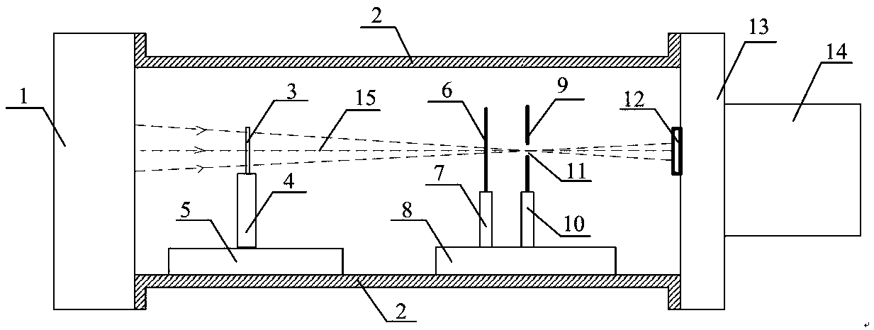
[0022] figure 1 It is a structural schematic diagram of the spatial resolution measuring device of the X-ray plane detector of the present invention, figure 2 Schematic diagram of the 10.0Lp / mm resolution plate. exist Figure 1~Figure 2 Among them, the spatial resolution measuring device of the X-ray plane detector of the present invention comprises an X-ray tube 1, a resolution plate 3, a filter plate 6 and an X-ray framing camera, and the X-ray framing camera is composed of a cathode microstrip 12, an Frame changing tube 13 and CCD camera 14 constitute, and cathode microstrip 12 is plated on the microchannel plate of frame changing tube 13, and frame changing tube 13 is closely coupled with CCD camera 14; Resolution plate 3 and A pinhole 11 is arranged between the X-ray framing cameras, and the central light 15 emitted by the X-ray generating device passes through the center of the resolution plate 3, the center of the filter 6, the pinhole 11, and the center of the catho...
Embodiment 2
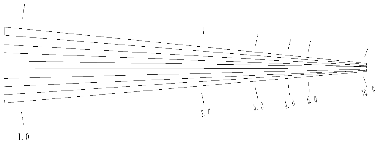
[0026] figure 1 It is a structural schematic diagram of the spatial resolution measuring device of the X-ray plane detector of the present invention, image 3 A schematic diagram of a fan-shaped resolution board. Except that the resolution plate 3 is different from the embodiment 1, other structures of the spatial resolution measuring device of the X-ray plane detector are the same. Such as image 3 As shown, the resolution board 3 in this embodiment is a fan-shaped resolution board, and the line pair density gradually changes from 1.0 Lp / mm to 10.0 LP / mm, and the corresponding scale values are indicated. Adjust the translation stage Ⅰ5 and translation stage Ⅱ8, set the imaging magnification M=0.2, the line pair bundle recorded by the CCD camera 9 is just indistinguishable at the scale value of 5.0Lp / mm, then the spatial resolution of the gated frame camera is 5.0Lp / mm÷0.2=25.0Lp / mm.
[0027] It can be understood that the line pair density of the resolution board in Emb...
PUM
 Abstract
Description
Claims
Application Information