Double disc coulter

A double-disc and disc plow technology, which is applied to plows, agricultural machinery and tools, and digging/covering trenches and holes, can solve the problems of inaccurate modeling, expensive, troublesome mass production, etc., and achieve the effect of easy manufacturing

Active Publication Date: 2016-04-20
LEMKEN
View PDF5 Cites 2 Cited by
  • Summary
  • Abstract
  • Description
  • Claims
  • Application Information

AI Technical Summary

Problems solved by technology

However, these methods are all either imprecise in modeling or cumbersome and expensive in mass production

Method used


Image

  • Double disc coulter
  • Double disc coulter
  • Double disc coulter

Examples


Embodiment Construction

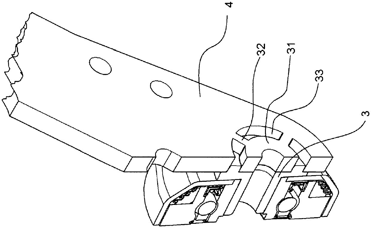
[0027] figure 1 A cross-sectional view of a double disc coulter is shown in perspective. The right-hand coulter disc is not shown for a better view of the coulter holder. The double-disc coulters 1 are connected laterally at a distance from other double-disk coulters (not shown) by means of a front borehole 11 in such a way that they can move vertically on the crossbeam by means of bearing elements , and the beam is connected with the main frame (Hauptrahme) of the distribution machine (Verteilmaschine). A vertical, movably connected post 12 to the coulter bar can exert pressure on the coulter bar 4 and the double disc coulter 1 with respect to the base by means of a spring or other force , so that it squeezes into the soil. Due to the V-shaped position of the disk coulters relative to one another, the soil is pushed apart in a V-shaped manner. The agricultural product can be introduced into this V-groove by means of an application line (Ausbringleitung) which protrudes in...


PUM


Abstract

A double disc coulter (1) has two disc coulters (2) which are angled in a V-shaped manner with respect to each other and are mounted rotatably on hollow axle stubs (3) by means of bearing units (18). A hollow axle stub (3) is arranged with a flange surface (5), which faces the coulter carrier (4), at an angle with respect to the vertical plane of the axis of rotation (6) of the hollow axle stub. At the same time, the hollow axle stub defines the angular position of the plane (13) which intersects the axis of rotation (6) and an axis (7) which is perpendicular to the flange surface (8, 9) of the coulter carrier (4).

Description

technical field [0001] The invention relates to a double disc coulter according to the preamble of claim 1 . Background technique [0002] Double disc coulters are used in particular for introducing agricultural products, such as seeds or manure, into the soil and are distinguished by their low clogging properties. Through the angled (angewinkelt) position of the disc coulters relative to each other, V-shaped furrows (furches) are formed into the soil into which agricultural products are inserted in liquid or solid form middle. For example EP1911340 discloses a kind of such double disc coulter. The previously known double disc coulters have in common that the position of the disc coulters is predetermined by the shape of the coulter holder. This is solved by beveled welding of the shaft ends or by mold-falling moldings, such as volume molding or shape casting. Of course, this can also be achieved by material-removing mechanical processing. However, these methods are all...

Claims


Application Information

Patent Timeline
Patent Type & Authority Applications(China)
IPC IPC(8): A01C5/06
CPCA01C5/064A01B15/18A01B71/04A01C7/20
Inventor M.格贝肯D.韦里斯C.佩森斯T.卢卡斯M.贝伦德森C.格岑M.格拉茨D.贝格尔富特
Owner LEMKEN
Why Eureka
Try Eureka