Stick glue container, stick glue, and refill
A technology for replacing boxes and glue sticks, applied in the field of replacement boxes, can solve the problems of shortened service life, difficult to stick closely, and obstacles in assembly and disassembly, and achieve the effect of improving air tightness
- Summary
- Abstract
- Description
- Claims
- Application Information
AI Technical Summary
Problems solved by technology
Method used
Image

Examples
no. 1 Embodiment approach
[0049] Figure 1 to Figure 7 )>
[0050] Below, refer to Figure 1 to Figure 7 A first embodiment of the present invention will be described.
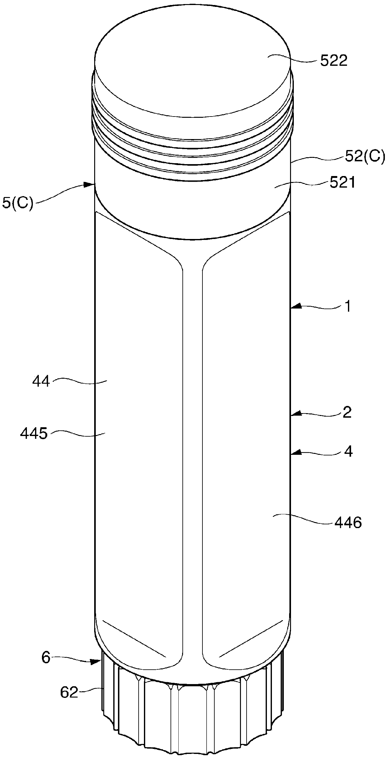
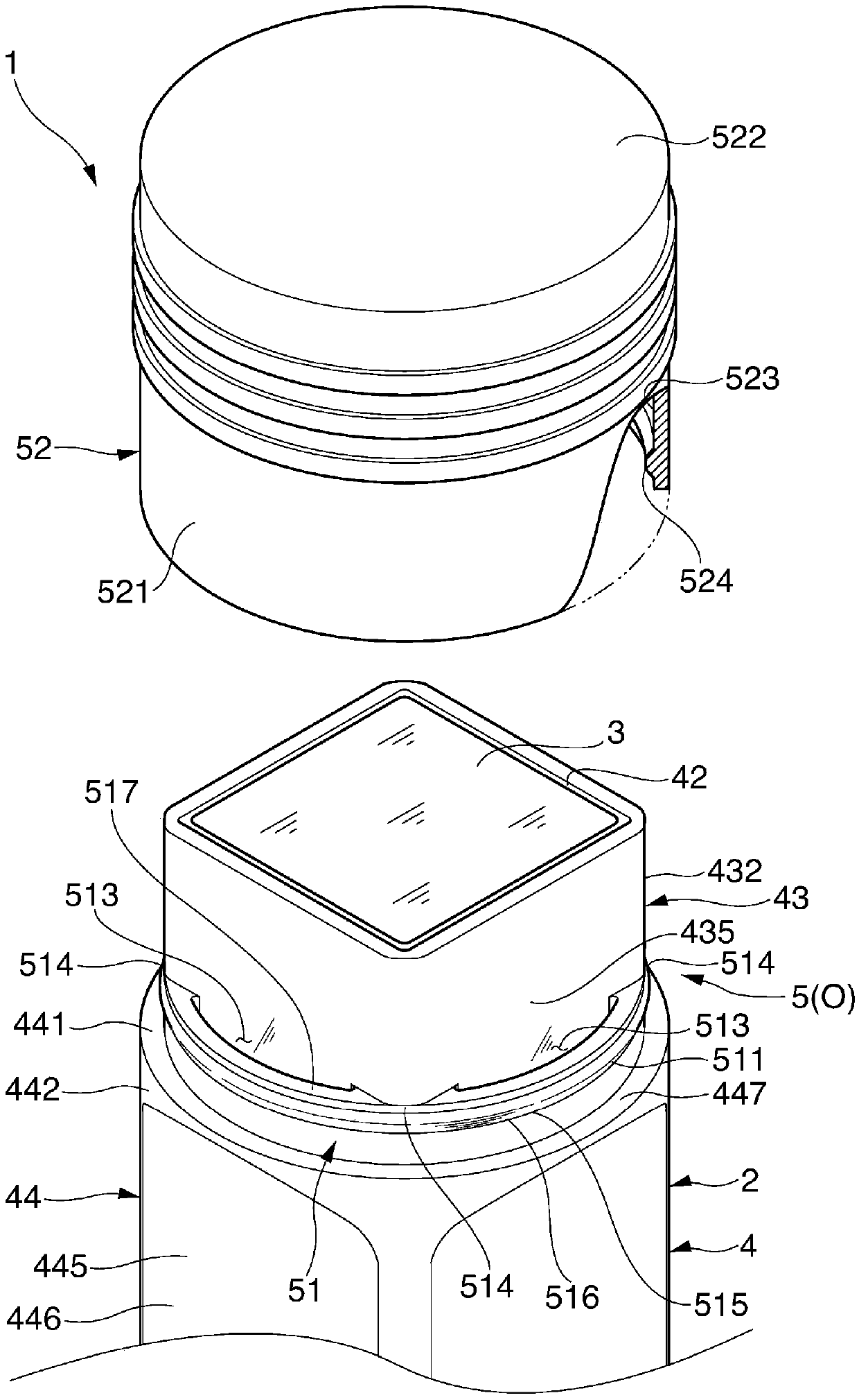
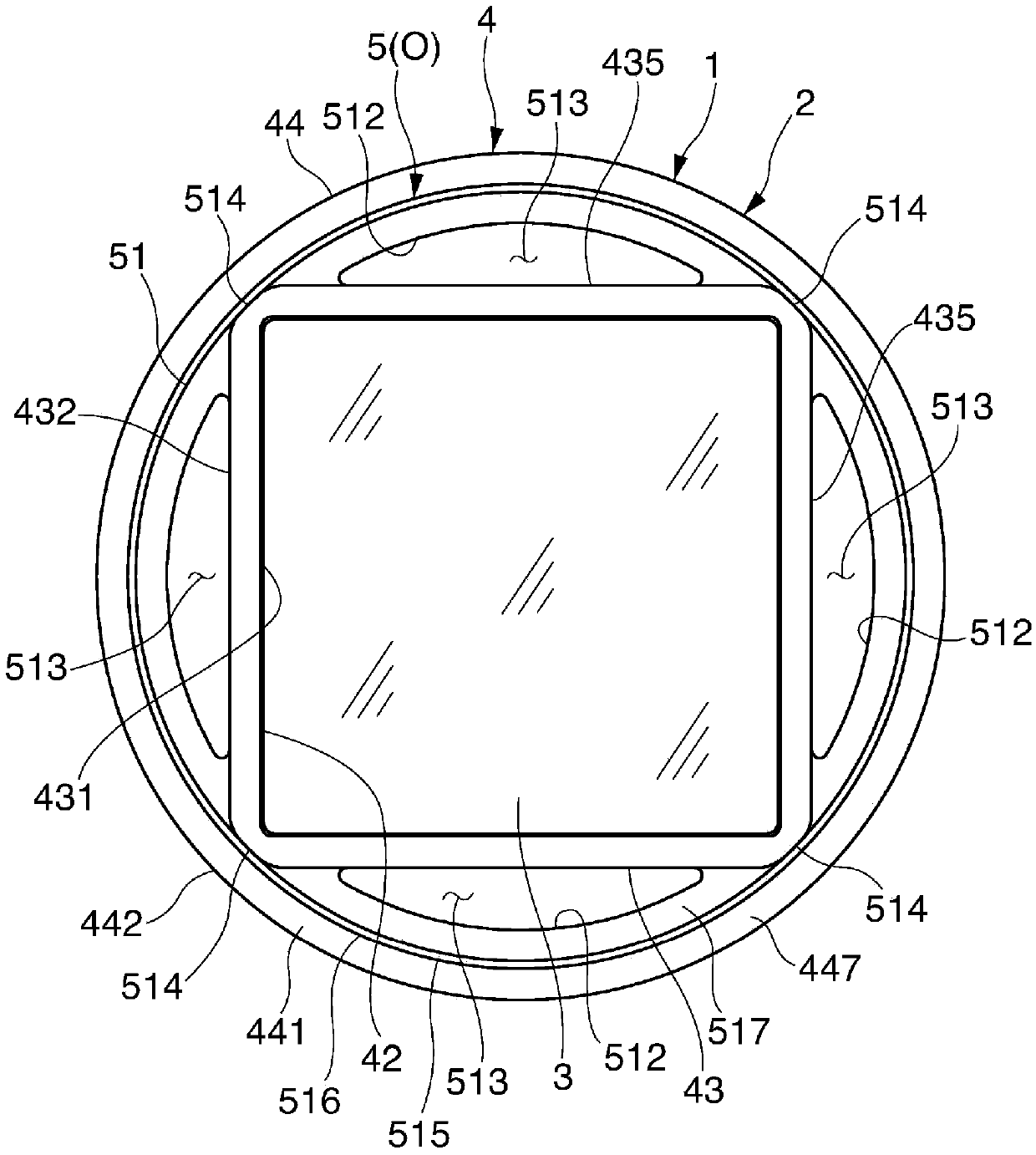
[0051] Such as Figure 1 ~ Figure 3 As shown, the glue stick 1 of this embodiment is filled with glue 3 in the container 2 .
[0052] Such as Figure 1 to Figure 7As shown, the above-mentioned container 2 is equipped with: a container main body 4, which has a glue filling space 41 for filling the glue 3 inside and has a non-circular glue outlet 42 at the top 441 for leading the above-mentioned glue 3 to the outside; The opening and closing mechanism 5 can be selectively placed in a closed state (C) in which the communication between the glue filling space 41 of the container main body 4 and the outside is airtightly cut off, and an open state (C) in which the above-mentioned glue 3 can be led out to the outside ( O) any state; and the glue push-out mechanism 6, which is used to make the above-mentioned glue 3 gradually lead out fro...
no. 2 Embodiment approach
[0069] Figure 8 , Figure 9 )>
[0070] Such as Figure 8 as well as Figure 9 As shown, the container 2 of the glue stick 1 of this embodiment is equipped with: a container main body 4, which has a glue filling space 41 for filling the glue 3 inside and has a non-perfect circle for making the above-mentioned glue 3 lead out to the outside at the top. The glue outlet 42; the opening and closing mechanism 5, which can be selectively placed in the closed state (C) that the glue filling space 41 of the container body 4 is airtightly cut off from the outside, and the above-mentioned glue 3 can be sent to the outside. Any shape state of the derived open state (O); and the glue pushing mechanism 6, which is used to make the above-mentioned glue 3 gradually lead out from the glue outlet 42.
[0071] Such as Figure 8 as well as Figure 9 As shown, the above-mentioned container main body 4 is provided with: the glue filling part 43 having the above-mentioned glue outlet 42 at th...
no. 3 Embodiment approach
[0082] Figure 10 )>
[0083] Next, refer to Figure 10 The glue stick 1 according to the third embodiment of the present invention will be described.
[0084] Such as Figure 10 As shown, the container 2 of the glue stick 1 of this embodiment is equipped with: a container main body 4, which has a glue filling space 41 for filling the glue 3 inside and has a non-perfect circle for making the above-mentioned glue 3 lead out to the outside at the top. The glue outlet 42; the opening and closing mechanism 5, which can be selectively placed in the closed state (C) that the glue filling space 41 of the container body 4 is airtightly cut off from the outside, and the above-mentioned glue 3 can be sent to the outside. Any state of the open state (O) derived; and the glue pushing mechanism 6 used to gradually lead the above-mentioned glue 3 from the glue outlet 42, only the structure of the replacement box 7 is different from the above-mentioned second embodiment.
[0085] Such as ...
PUM
 Abstract
Description
Claims
Application Information
 - Generate Ideas
- Intellectual Property
- Life Sciences
- Materials
- Tech Scout
- Unparalleled Data Quality
- Higher Quality Content
- 60% Fewer Hallucinations
Browse by: Latest US Patents, China's latest patents, Technical Efficacy Thesaurus, Application Domain, Technology Topic, Popular Technical Reports.
© 2025 PatSnap. All rights reserved.Legal|Privacy policy|Modern Slavery Act Transparency Statement|Sitemap|About US| Contact US: help@patsnap.com