Reboiler for supergravity rectification

A high-gravity rectification and reboiler technology, which is applied in fractionation, distillation separation, chemical instruments and methods, etc., can solve the problem of low heat exchange area and heat exchange efficiency of reboiler, difficulty in maintenance and replacement of heat exchange tubes, insufficient The use of heat energy and other issues, to achieve the effect of convenient regular inspection and maintenance, conducive to heat exchange efficiency, and small footprint

Active Publication Date: 2016-04-27
KUNMING UNIV OF SCI & TECH
View PDF8 Cites 1 Cited by
  • Summary
  • Abstract
  • Description
  • Claims
  • Application Information

AI Technical Summary

Problems solved by technology

[0005] The reboiler mainly has the following two major disadvantages: first, the heat transfer area and heat transfer efficiency of the reboiler are low, and the heat energy cannot be fully utilized; Seriously restrict the normal operation of production
[0006] The utility model patent No. CN104096368A discloses a reboiler, which inserts one end of the heat exchanger tube into the reboiler shell and connects the other end to the end through the reboiler shell. The purpose of easy maintenance and replacement of the heat exchanger is achieved, but due to the small heat transfer area of ​​the heat exchange tube, there are disadvantages of low heat transfer efficiency and inability to fully utilize heat energy
[0007] The invention patent with the patent number of CN104059687A discloses a reboiler, which has guide chambers at both ends of the reboiler and a heating chamber in the middle, and adopts a multi-layer heat exchange method to improve the heat transfer efficiency of the reboiler. purpose, but because the heat exchange tube is completely fixed in the heating chamber, it is difficult to maintain and replace the heat exchange tube.

Method used


Image

  • Reboiler for supergravity rectification
  • Reboiler for supergravity rectification
  • Reboiler for supergravity rectification

Examples


Embodiment 1

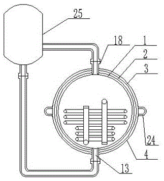
[0045] Such as Figure 1 to 9 As shown, the reboiler for high gravity rectification includes a reboiler and a rectification tower 25. The top of the reboiler is provided with a material gas phase outlet 18 and the bottom is provided with a natural reflux liquid inlet 13, and the material gas phase outlet 18 is connected to the rectification On the side of the tower 25, the natural reflux inlet 13 is connected to the bottom of the rectification tower 25;

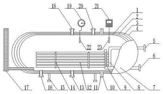
[0046] The reboiler includes a reboiler shell 1, an end cover 7, a heat exchange tube support frame 14, a shell support frame 15, a waste liquid discharge outlet 16, a material inlet 20, and heat exchange components. The reboiler shell 1 There is a material inlet 20 at the top and a waste liquid discharge outlet 16 at the bottom. A housing support frame 15 is provided at the bottom of the reboiler housing 1, and the reboiler housing 1 passes through a flange interface. 10 and flange interface 11 is connected to the end cover 7...

Embodiment 2

[0049] The reboiler for high-gravity rectification includes a reboiler and a rectification tower 25. The top of the reboiler is provided with a material gas phase outlet 18 and a natural reflux liquid inlet 13 at the bottom. The material gas phase outlet 18 is connected to the rectification tower 25. On the side, the natural reflux inlet 13 is connected to the bottom of the rectification tower 25;

[0050] The reboiler includes a reboiler shell 1, an end cover 7, a heat exchange tube support frame 14, a shell support frame 15, a waste liquid discharge outlet 16, a material inlet 20, and heat exchange components. The reboiler shell 1 There is a material inlet 20 at the top and a waste liquid discharge outlet 16 at the bottom. A housing support frame 15 is provided at the bottom of the reboiler housing 1, and the reboiler housing 1 passes through a flange interface. 10 and flange interface 11 is connected to the end cover 7. The wall surface of the end cover 7 is provided with a h...

Embodiment 3

[0053] The reboiler for high-gravity rectification includes a reboiler and a rectification tower 25. The top of the reboiler is provided with a material gas phase outlet 18 and a natural reflux liquid inlet 13 at the bottom. The material gas phase outlet 18 is connected to the rectification tower 25. On the side, the natural reflux inlet 13 is connected to the bottom of the rectification tower 25;

[0054] The reboiler includes a reboiler shell 1, an end cover 7, a heat exchange tube support frame 14, a shell support frame 15, a waste liquid discharge outlet 16, a material inlet 20, and heat exchange components. The reboiler shell 1 There is a material inlet 20 at the top and a waste liquid discharge outlet 16 at the bottom. A housing support 15 is provided at the bottom of the reboiler housing 1, and the reboiler housing 1 passes through a flange interface. 10 and flange interface 11 is connected to the end cover 7. The wall surface of the end cover 7 is provided with a heating...


PUM


Abstract

The invention relates to a reboiler for supergravity rectification, and belongs to the technical field of a chemical heating device. The device comprises the reboiler and a rectifying tower, wherein a material gas phase outlet in the reboiler is connected with one side of the rectifying tower; a natural return flow inlet in the reboiler is connected with the bottom part of the rectifying tower; a reboiler shell in the reboiler is connected with an end cover through a flange connector, a heat exchange component comprises an outlet collecting pipe, an inlet collecting pipe and a plurality of snakelike heat exchange pipes, rows of even number of snakelike heat exchange pipes are arranged on the outlet collecting pipe and the inlet collecting pipe from up to down and are respectively communicated with the outlet collecting pipe and the inlet collecting pipe, the snakelike heat exchange pipes are mounted at the inner part of the reboiler shell through heat exchange pipe support frames, the outlet collecting pipe and the inlet collecting pipe are respectively in airtight connection with a heating steam outflow pipe and a heating steam inflow pipe outlet of the end cover. The reboiler for supergravity rectification can improve reboiler heat exchange efficiency and fully use the heat energy and is easy in maintenance and replacement of a heat exchanger.

Description

Technical field [0001] The invention relates to a reboiler for supergravity rectification and belongs to the technical field of chemical heating devices. Background technique [0002] The high-gravity distillation technology is a new type of separation technology. The technology relies on the high-gravity distillation tower. Its principle is: the liquid is stretched into a film into filaments and drops under the action of high gravity and huge shearing force. A huge contact area between the phases is generated, which increases the gas-liquid contact area by several orders of magnitude, so as to achieve the purpose of greatly improving the gas-liquid mass transfer efficiency. Compared with the traditional distillation method, this method is more refined, safer and more efficient, has significant energy-saving effects, and is more adaptable to the environment and enterprise requirements. [0003] The reboiler is a special heat exchanger that can exchange heat and has space for gasif...

Claims


Application Information

Patent Timeline
Patent Type & Authority Applications(China)
IPC IPC(8): B01D3/30B01D3/32
CPCB01D3/30B01D3/322
Inventor 周俊文任晓鹏常军张利波彭金辉李世伟
Owner KUNMING UNIV OF SCI & TECH
Why Eureka
Try Eureka