Efficient air cooling device

An air-cooling device and high-efficiency technology, used in workpiece cooling devices, workpiece surface treatment equipment, metal rolling, etc., can solve the problem of uniformity of the upper surface of the wire, which needs to be improved, the lower surface cannot be uniformly sprayed, and the upper and lower surfaces of the wire are cooled. Non-uniformity and other problems, to achieve the effect of facilitating later equipment maintenance, improving production flexibility, and improving the competitiveness of enterprises

Active Publication Date: 2016-04-27
CISDI ENG CO LTD
View PDF9 Cites 6 Cited by
  • Summary
  • Abstract
  • Description
  • Claims
  • Application Information

AI Technical Summary

Problems solved by technology

The problem with this method is: the mist can only be sprayed on the upper surface of the wire, and the lower surface cannot be uniformly sprayed and cooled, the upper and lower surfaces of the wire are cooled unevenly, and the water mist cooling will cause rust spots on the upper surface of the steel.
[0006] (2) The Chinese patent with publication number 101480669 discloses a "cooling method and cooling device for high-speed wire rod mill Stelmore line". The main problem is: in order to ensure the cooling intensity, the fan below the Stelmore line needs to maintain a certain angle with the outlet of the upper fan, and the air volume of the upper fan needs to be much smaller than the air volume of the lower fan.
Although this method solves the problem of the small air volume of the previous fans, since all the fans blow from the bottom to the top, the uniformity of the upper surface, lower surface, and overlapping points of the wire still needs to be improved.
[0008] In order to fundamentally solve the problems of insufficient air-cooling strength, low cooling speed and uneven cooling existing in the existing high-speed wire rod Stelmore air-cooled line, the present invention provides a high-efficiency air-cooling device for high-speed wire rods, which can effectively Improve the cooling strength of the air-cooled line and the cooling uniformity of the wire, thereby improving the performance of the wire product and improving the economic benefits of the enterprise

Method used


Image

  • Efficient air cooling device
  • Efficient air cooling device
  • Efficient air cooling device

Examples


Embodiment 1

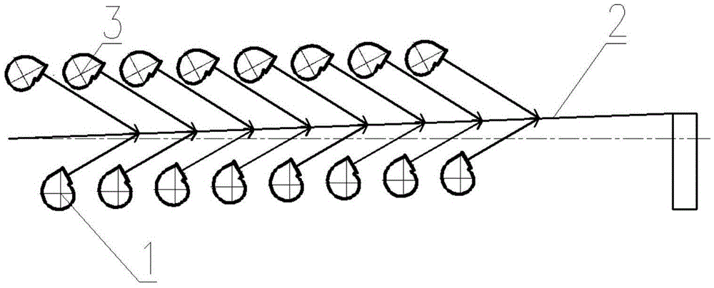
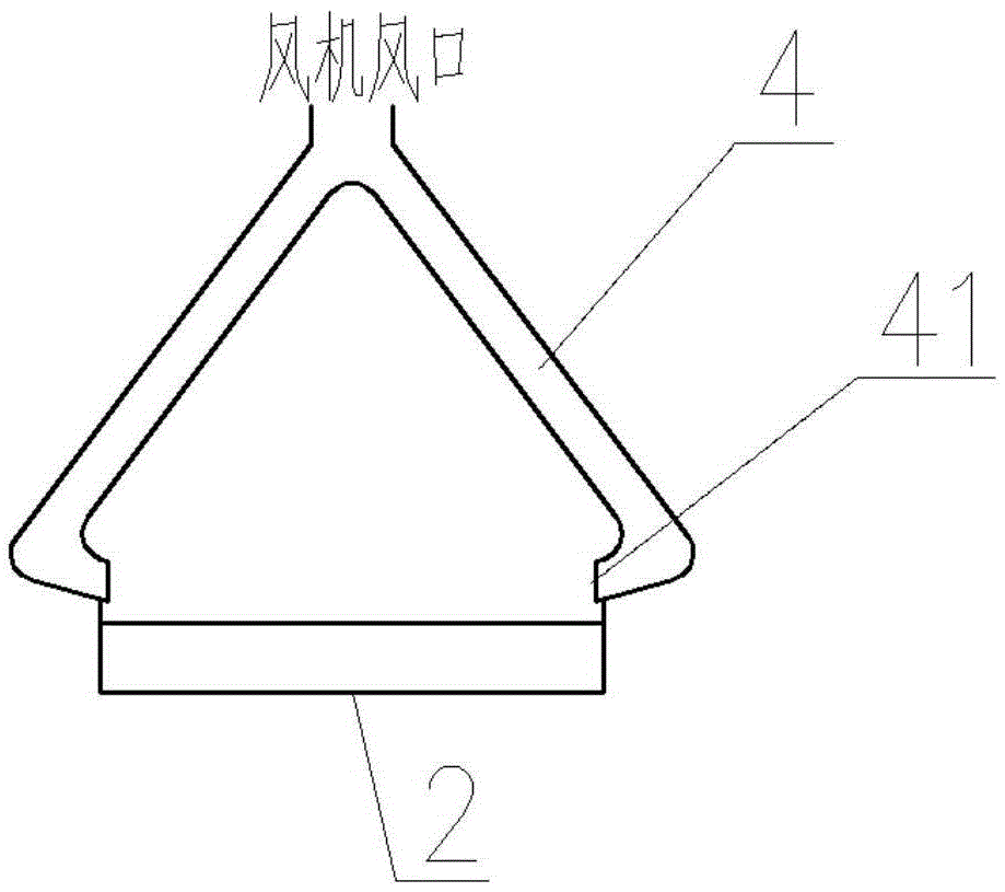
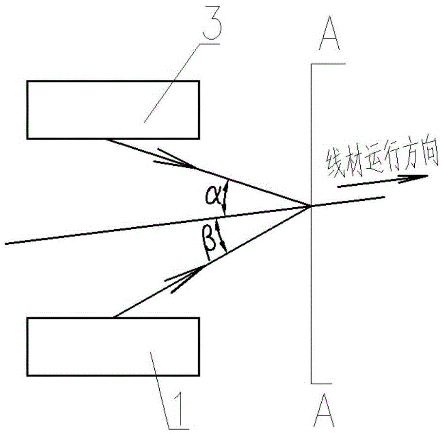
[0032] Such as figure 1 , figure 2 , image 3 , Figure 4 , Figure 5 and Figure 6 As shown, when the off-line fan 1 of the high-speed wire Stelmo air-cooled line is a 45° inclined fan, 6 to 16 sets of off-line fans 3 are arranged in sequence under the air-cooled roller table 2 of the Stelmo air-cooled line along the wire running direction At the same time, 6 to 16 fans 3 are correspondingly arranged on one side of the lower fan 1 or above the air-cooled roller table 2, and the fans 3 send air to the wire through the blowing duct 4 for cooling. The blowing pipe 4 has two air outlets 41 and the two air outlets are correspondingly located on both sides of the air-cooled roller table 2. The angle α between the blowing pipe 4 and the air-cooled roller table 2 in the wire running direction is 15° to 90°. The angle γ between the side blowing direction and the air-cooled roller table 2 is 0-90°. By controlling the layout position and air supply angle of the blowing duct 4, it...

Embodiment 2

[0040] Such as Figure 7 , Figure 8 and Figure 4 As shown, when the off-line fan 1 of the high-speed wire rod Stelmore air-cooling line is a vertical fan, 8 to 12 down-fan fans are arranged in turn along the running direction of the wire rod under the air-cooling roller table of the Stelmore air-cooling line, and at the same time 8 to 12 fans 3 are correspondingly arranged on one side of the fan or above the air-cooled roller table 2, and the fans send air to the wire through the blowing duct for cooling. The blowing pipe has two air outlets and the two air outlets are located on both sides of the air-cooled roller table. The angle α between the blowing pipe and the air-cooled roller table in the direction of wire rod running is 15°-90°. The angle γ between the air-cooled roller tables is 0-90°. By controlling the layout position of the blowing duct and the air supply angle, it can ensure that the cooling air blown by the fan can completely cover the wire coil, which can ...

Embodiment 3

[0043] When the off-line fan of the high-speed wire rod Stelmo air-cooled line is a vertical fan, 10 to 14 down-fans are arranged in turn along the wire running direction under the air-cooled roller table of the Stelmo air-cooled line, and at the same time, on the side of the down-fan Or 10 to 14 fans are correspondingly arranged above the air-cooled roller table, and the fans send air to the wire through the blowing duct for cooling. The blowing pipe has two air outlets and the two air outlets are located on both sides of the air-cooled roller table. The angle α between the blowing pipe and the air-cooled roller table in the direction of wire rod running is 30°-60°. The angle γ between the air-cooled roller tables is 15-70°. By controlling the layout position of the blowing duct and the air supply angle, it can ensure that the cooling air blown by the fan can completely cover the wire coil, which can effectively improve the cooling strength of the air-cooled line and the cool...


PUM


Abstract

The invention discloses an efficient air cooling device. The efficient air cooling device comprises draught fans and lower draught fans arranged below an air cooling roller way, and further comprises an air blowing pipeline with two air outlets. The air blowing pipeline and the draught fans are connected, and the two air outlets are located on the two sides of the air cooling roller way. The included angle of the air blowing pipeline and the air cooling roller way in the wire moving direction is 15 degrees to 90 degrees. The included angle of the air blowing pipeline and the air cooling roller way in the side air blowing direction is 0 degree to 90 degrees. According to the efficient air cooling device, by controlling the layout position and the air feeding angle of the air blowing pipeline, it can be ensured that all wire coils are covered with cooling air blown out of the draught fans; the cooling intensity and the wire cooling uniformity of an air cooling line can be improved effectively, so that the wire product performance is improved, and the problems that existing high speed stelmor air cooling lines for wires are insufficient in air cooling intensity, low in cooling speed and uneven in cooling are solved.

Description

technical field [0001] The invention belongs to the field of iron and steel metallurgy, and in particular relates to a high-efficiency air cooling device. Background technique [0002] As one of the important products in the iron and steel industry, wire rod is widely used in construction, machinery and metal products industries. In recent years, the output has continued to increase, reaching 153.8 million tons in 2015, accounting for 13.7% of China's steel output. [0003] At present, the typical process layout of high-speed wire rod is heating furnace, roughing mill, intermediate rolling mill, pre-finishing mill, finishing mill, reducing and sizing, spinning, air-cooling line, and coil collection. The cooling method after spinning mainly adopts Steyr (Stelmor) air-cooled line. The air-cooled line is composed of a conveying roller table line composed of heat-resistant steel rollers. Set up the insulation cover. The wire is spun into a loop, evenly distributed on the Stel...

Claims


Application Information

Patent Timeline
Patent Type & Authority Applications(China)
IPC IPC(8): B21B45/02
CPCB21B45/0209B21B2045/0212
Inventor 周民韩会全杨春楣马靳江牛强
Owner CISDI ENG CO LTD
Why Eureka
Try Eureka