High-precision drill bit

A high-precision, drill bit technology, applied in the direction of drill repair, twist drill, drilling tool accessories, etc., can solve the problems of easy chipping of the shaft guide strip, reduce the guiding effect of the shaft guide strip, increase the cutting load and cutting vibration, etc., to achieve Improve processing efficiency and surface processing quality, improve guiding ability and surface quality finishing ability, and reduce load

Active Publication Date: 2016-04-27
ZHUZHOU CEMENTED CARBIDE CUTTING TOOLS CO LTD
View PDF6 Cites 9 Cited by
  • Summary
  • Abstract
  • Description
  • Claims
  • Application Information

AI Technical Summary

Problems solved by technology

However, when the contact area between the shaft guide strip and the processing surface is too large, severe friction will occur between the shaft guide strip and the processing surface, which will greatly increase the cutting load and cause severe cutting vibration. However, if the shaft guide strip and the processing surface contact area are reduced, the shaft guide When the bar is designed to be narrow, it will reduce the guiding effect of the shaft guide bar and reduce the surface processing quality. At the same time, the narrow shaft guide bar is prone to chipping when cutting

Method used


Image

  • High-precision drill bit
  • High-precision drill bit
  • High-precision drill bit

Examples


Embodiment 1

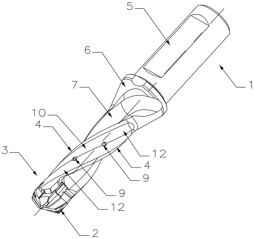
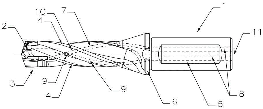
[0034] Figure 1 to Figure 3 The first embodiment of a high-precision drill bit of the present invention is shown, which is composed of a cutter body 1 and a cutting blade 2. The cutter body 1 consists of a shank 5, a cutting end 3, and a The cutting blade 2 is loaded and unloaded by the cutter body 1 through the elastic deformation caused by the sipe 16. The cutter body 1 is provided with a shank 5 that flows through the peripheral surface 6 and communicates with the cutting end 3. The cooling channel 8, the peripheral surface 6 is provided with two chip pockets 7 for discharging chips, and the single peripheral surface 6 between the two chip pockets 7 is provided with a shaft guide strip group, and each shaft guide strip group includes two When the shaft guide bar 4 and the cutting blade 2 are processed, the shaft guide bar 4 can guide the high-precision drill bit from the axial and radial directions, and the adjacent shaft guide bar 4 is formed between the peripheral surfac...

Embodiment 2

[0039] Figure 4 to Figure 6 The second embodiment of a high-precision drill bit of the present invention is shown. The difference between this embodiment and the first embodiment is that the cutter body 1 and the cutting blade 2 are not detachable and integrally formed. The high-precision drill bit is composed of the cutter body 1. The cutting insert 2 is located on the cutting end 3 of the cutter body 1 without additional fasteners 15 , and the rest of the parts that are not described are exactly the same as those in Embodiment 1, and will not be repeated here.

Embodiment 3

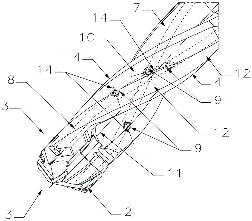
[0041] Figure 7 to Figure 9 The third embodiment of a high-precision drill bit of the present invention is shown. The difference between this embodiment and the second embodiment is that the chip flute 7 on the cutter body 1 has no helix angle and is arranged parallel to the rotation center axis 11. It is linear, and the rest of the details are the same as those in Embodiment 2, and will not be repeated here.


PUM


Abstract

The invention discloses a high-precision drill bit, comprising a tool body and cutting blades; the tool body is composed of a shank portion, a cutting end portion and a peripheral surface located between the shank portion and the cutting end portion; the cutting blades are located on the cutting end portion; a cooling channel penetrating from the shank portion to the cutting end portion is formed in the tool body; a chip pocket for removing chips is formed in the peripheral surface; shaft guiding bar groups are arranged at positions, corresponding to every cutting blades, on the peripheral surfaces; each shaft guiding bar group comprises at least two shaft guiding bars; every two adjacent shaft guiding bars in each shaft guiding bar group, the peripheral surface and a surface machined define a sealing region; at least one communicating hole is formed in each part, between every two adjacent shaft guiding bars in each shaft guiding bar group, of the peripheral surface; and each communicating hole communicates with the cooling channel. The high-precision drill bit has the characteristics of low circumferential stress on each shaft guiding bar, high precision and long service life.

Description

technical field [0001] The invention relates to a high-precision drill bit, in particular to a vibration-resistant high-precision drill bit with a plurality of guide bar structures for high-precision processing. Background technique [0002] When the high-precision drill bit is cutting, the cutting end is mainly subjected to cutting force, and the chips can only be discharged from the cutting end through the chip groove. Quickly discharged from the chip flute, the chip flute generally has a large chip space, so the ratio between the core thickness of the chip flutes on the peripheral surface of the high-precision drill bit and the diameter of the high-precision drill bit is small, and the changing deflection It is easy to cause the cutting end to vibrate following the low-strength peripheral surface. In order to reduce the vibration of the tool during the machining of the connecting hole, people set one or more shaft guide strips around the high-precision drill bit, and the ...

Claims


Application Information

Patent Timeline
Patent Type & Authority Applications(China)
IPC IPC(8): B23B51/02B23B51/06
CPCB23B51/02B23B51/06B23B2251/408
Inventor 江爱胜王社权刘敏易为李屏
Owner ZHUZHOU CEMENTED CARBIDE CUTTING TOOLS CO LTD
Why Eureka
Try Eureka