
Swaying traction system and method for platforms

A traction system and platform technology, applied in the field of working condition simulation test, can solve problems such as friction loss, leakage loss, system stability, and unsuitable for long-distance transmission, and achieve the effect of low cost, simple structure, and far-reaching practical engineering application value

Inactive Publication Date: 2016-04-27
CHINA UNIV OF MINING & TECH
View PDF7 Cites 2 Cited by
  • Summary
  • Abstract
  • Description
  • Claims
  • Application Information

AI Technical Summary

Problems solved by technology

[0004] At present, the working condition simulation test platform with two degrees of freedom of lateral swing and longitudinal swing generally uses hydraulic cylinders as the drive system. However, the hydraulic drive system uses liquid as the working medium, and there will inevitably be leakage during operation. Affect the stability of the overall operation of the system; the hydraulic system has a lot of energy loss during the working process, such as friction loss, leakage loss, etc., so it is not suitable for long-distance transmission; the hydraulic system is sensitive to oil temperature changes, oil temperature changes will Affect the stability of the movement; the response of the hydraulic system is slow and the operation is not sensitive

Method used


Image

  • Swaying traction system and method for platforms
  • Swaying traction system and method for platforms
  • Swaying traction system and method for platforms

Examples


Embodiment Construction

[0035] The present invention will be further described below in conjunction with accompanying drawing.

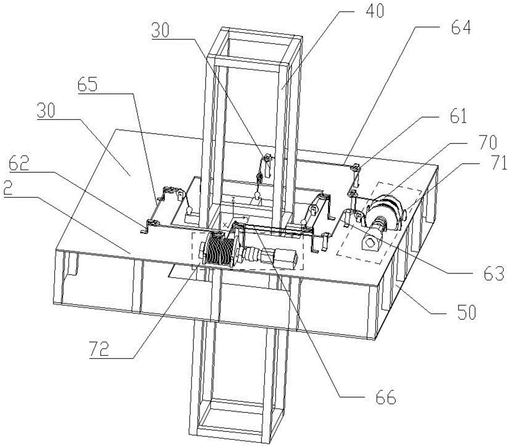
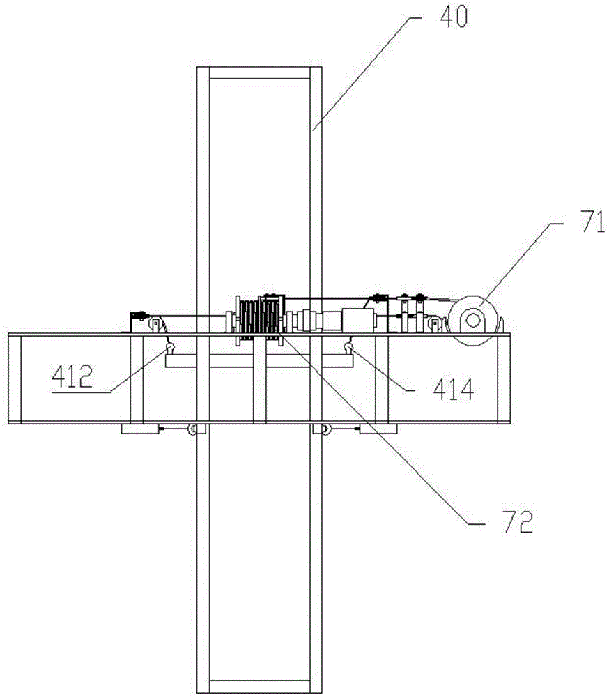
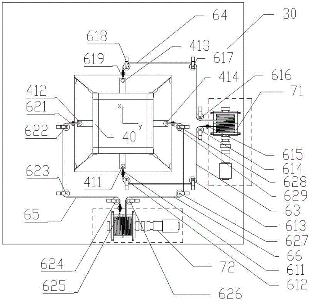
[0036] Such as Figure 1 to Figure 8 Shown: the present invention includes vertically arranged truss platform 2 and the derrick 40 passing through the through hole of truss platform 2 longitudinally; Drive system 70, four stabilizing systems 90 arranged on the lower platform 50 of the truss platform 2; the coordinate axis XYZ is established with the center of the derrick 40, and the XYZ center plane of the derrick 40 coincides with the XYZ center plane of the truss platform 2 during initial setting;

[0037] The reel drive system 70 includes the first reel drive system 71 and the second reel drive system 72; the guide traction system includes the pulley guide system 61 on the XZ, the pulley guide system 62 on the YZ, the first drive wire rope 63, the second drive Wire rope 64, the third driving wire rope 65 and the fourth driving wire rope 66; the derrick 40 is fixed with ...


PUM


Abstract

The invention discloses a swaying traction system and method for platforms. The swaying traction system comprises a truss platform arranged vertically, a derrick penetrating through the truss platform in the longitudinal direction, a guide traction system arranged on an upper platform of the truss platform, winding drum drive systems driven by an electric motor and four stable systems arranged on a lower platform of the truss platform; coordinate axes XYZ are established on the basis of the center of the derrick, and the XYZ central planes of the derrick overlap with the XYZ central planes of the truss platform in initial setting; steel wire ropes form a traction circulation system, and the upper platform is provided with the winding drum drive systems driving the steel wire ropes to synchronously move in one or two axial directions of the X axis or the Y axis of the local coordinate system XOY. By arranging the stable systems, the derrick can bear certain tension, can be operated smoothly in the swaying process and does not shake. The swaying traction system and method for the platforms have the beneficial effects that the structure is simple, the work space is large and the practical engineering application value is high.

Description

technical field [0001] The invention relates to a platform swing traction system and method, which are specifically used for the simulation test of working conditions of two degrees of freedom of rolling and pitching of construction shaft platforms, marine elevator derricks and other platforms. Background technique [0002] The construction shaft platform is an important construction equipment in shaft construction. It is not only a construction operation panel, but also an equipment installation panel. Whether it can operate safely will directly affect the quality, progress and safety of shaft construction. During the lifting process of the construction vertical well platform, it is easy to cause uneven elongation of the suspension rope due to the eccentricity of the center of mass, which will cause the platform to tilt and chuck; or the deflection of the platform during the lowering process will cause a major accident of the platform colliding with the well wall. In the ea...

Claims


Application Information

Patent Timeline
Patent Type & Authority Applications(China)
IPC IPC(8): B66D1/12B66D1/28B66D1/30B66D1/60
CPCB66D1/12B66D1/28B66D1/30B66D1/60B66D2700/0183
Inventor 曹国华王磊朱真才王乃格彭维红李伟沈刚周公博刘善增彭玉兴
Owner CHINA UNIV OF MINING & TECH
Learn More