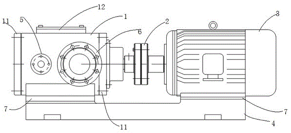
Screw pump for pitch conveying

A screw pump and asphalt technology, applied in the direction of pumps, pump components, rotary piston pumps, etc., can solve the problems of affecting the use efficiency, reducing the pumping capacity, shortening the service life, etc., to achieve the convenience of assembly and disassembly and replacement of components, and the use of low power. , the effect of large flow

Inactive Publication Date: 2016-04-27
太仓液压元件有限公司
View PDF7 Cites 5 Cited by
  • Summary
  • Abstract
  • Description
  • Claims
  • Application Information

AI Technical Summary

Problems solved by technology

[0002] Asphalt construction equipment is widely used in the construction or maintenance of highway traffic, municipal construction, and airport runways in my country. Asphalt gear pumps are key components of asphalt pumping systems for asphalt construction equipment. There are three main problems with existing asphalt gear pumps. One problem is that there are defects in the structural design of the active and passive gears. The first defect is that the shaft ends and teeth of the driving gear and the driven gear adopt a split structure, resulting in low overall strength and reduced service life. The second defect is that the tooth root is prone to narrow chip grooves Shallow, resulting in small particle size, especially in the application of rubber asphalt, which reduces the pumping capacity. The third problem is that the heat conduction efficiency is low, especially during the construction process in the colder northern regions. When the equipment is shut down Start the equipment again after a period of time, the asphalt inside the asphalt pump has solidified, you need to use a heat conduction plate to melt the asphalt before starting the pump, low heat conduction efficiency will directly affect the use efficiency

Method used


Image

  • Screw pump for pitch conveying

Examples


Embodiment Construction

[0015] The present invention will be described in detail below in conjunction with specific embodiments, but at the same time it is explained that the protection scope of the present invention is not limited to the specific scope of this embodiment. All other embodiments obtained below all belong to the protection scope of the present invention.

[0016] It should be noted that, in the description of the present invention, unless otherwise specified, the meaning of "plurality" is two or more; the terms "upper", "lower", "left", "right", "inner ", "outside", "front end", "rear end", "head", "tail", etc. indicate the orientation or positional relationship based on the orientation or positional relationship shown in the drawings, and are only for the convenience of describing the present invention and Simplified descriptions, rather than indicating or implying that the device or element referred to must have a particular orientation, be constructed and operate in a particular ori...


PUM


Abstract

The invention discloses a screw pump for pitch conveying. The screw pump comprises a screw pump body, a coupler, a motor and a base, wherein the screw pump body and the motor are fixed to the base with bolts; heat preservation layers are arranged at the two sides of the screw pump body through first flanges; a cover plate is arranged at the upper end of the screw pump body; a mechanical sealing layer is arranged between the cover plate and the upper end of the screw pump body; and an oil filling hole and a relief valve are formed in and arranged at the upper end of the screw pump body.

Description

technical field [0001] The invention belongs to the technical field of asphalt transportation, and in particular relates to a screw pump for asphalt transportation. Background technique [0002] Asphalt construction equipment is widely used in the construction or maintenance of highway traffic, municipal construction, and airport runways in my country. Asphalt gear pumps are key components of asphalt pumping systems for asphalt construction equipment. There are three main problems with existing asphalt gear pumps. One problem is that there are defects in the structural design of the active and passive gears. The first defect is that the shaft ends and teeth of the driving gear and the driven gear adopt a split structure, resulting in low overall strength and reduced service life. The second defect is that the tooth root is prone to narrow chip grooves Shallow, resulting in small particle size, especially in the application of rubber asphalt, which reduces the pumping capacity....

Claims


Application Information

Patent Timeline
Patent Type & Authority Applications(China)
IPC IPC(8): F04C11/00F04C13/00F04C2/16F04C15/00
CPCF04C11/00F04C2/16F04C13/001F04C15/00F04C15/0003F04C15/0061F04C15/0088F04C15/0096F04C2210/10
Inventor 施昌付
Owner 太仓液压元件有限公司
Why Eureka
Try Eureka