Electric mechanism for disconnecting switch for electrified railway contact net

A technology for electrified railways and isolating switches, which is applied to the power device inside the switch, etc., can solve the problems of circuit breaker malfunction, false display, and refusal to operate, etc., and achieves the effect of stable and reliable support, wide application range and long service life.

Active Publication Date: 2016-04-27
HEBEI YUNIU ELECTRICAL EQUIP
View PDF8 Cites 0 Cited by
  • Summary
  • Abstract
  • Description
  • Claims
  • Application Information

AI Technical Summary

Problems solved by technology

However, the remote control terminal will be interfered by various electromagnetic waves in the environment during actual work, so it will issue wrong instructions, resul

Method used


Image

  • Electric mechanism for disconnecting switch for electrified railway contact net
  • Electric mechanism for disconnecting switch for electrified railway contact net
  • Electric mechanism for disconnecting switch for electrified railway contact net

Examples


Embodiment 1

[0028] Embodiment 1 Electrified Railway Catenary Isolation Switch Electric Mechanism

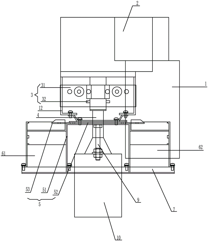
[0029] This embodiment provides a kind of electrified railway catenary isolating switch mechanism, which is used to make the opening circuit breaker 61 and closing circuit breaker 62 of the isolating switch act in time-sharing, such as figure 1 As shown, it includes: a motor 1 that provides power under the control of an electric operating mechanism, a reducer 2 driven by the motor 1, wherein the motor 1 can perform forward or reverse rotation under the control of the electric operating mechanism, and the reducer 2 has The preset limit angle of forward rotation and reverse rotation, when the reducer 2 rotates to the limit angle, the limit assembly 3 fixed on the reducer restricts it from continuing to rotate, and sends a position signal to the electric operating mechanism, and the electric operating mechanism drives the motor 1 Rotate in the opposite direction of the previous rotation; the ...

Embodiment 2

[0041] Embodiment 2 Electrified Railway Catenary Isolation Switch Electric Mechanism

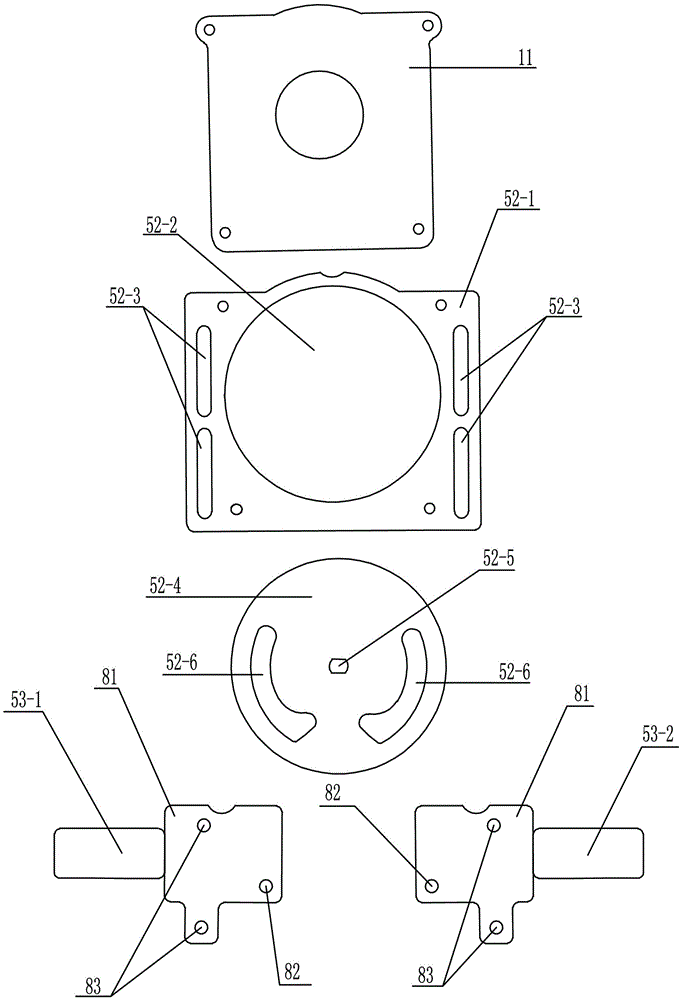
[0042] This embodiment provides an electrified railway catenary isolating switch electrical mechanism, which is used to make the opening circuit breaker 61 and closing circuit breaker 62 of the isolating switch act in time-sharing. The difference is that the structure of the turntable 52-4 in this embodiment, the turntable 52-4 in this embodiment is as Figure 4 As shown, it is also a disc-shaped structure, and two arc-shaped notches 52-7 are provided on the turntable 52-4, and the two arc-shaped notches 52-7 are arranged symmetrically with the diameter of the turntable 52-4 as the axis of symmetry. And the curvature of the two arc-shaped notches 52-7 is the same as that of the turntable 52-4. Similarly, in order to enable the arc-shaped notches 52-7 to apply thrust to the first protrusion 82, the two arc-shaped notches 52-7 in this implementation The adjacent ends are respectively concav...


PUM


Abstract

The invention provides an electric mechanism for a disconnecting switch for an electrified railway contact net. On the basis of control of an electric operating mechanism, the electric mechanism comprises a motor and a speed reducer, wherein the motor is used for providing power; the speed reducer has preset positive rotation limit angle and reverse rotation limit angle; when the speed reducer rotates to the limit angles, further rotation is limited by a limiting component fixed on the speed reducer and a position signal is sent out to the electric operating mechanism; a power output end of the speed reducer is connected with and provided with a change-over switch mechanism; and the change-over switch mechanism can start closing of a breaking breaker and breaking of a closing breaker in a time-sharing manner, or simultaneously start closing of the closing breaker and breaking of the breaking breaker in the time-sharing manner. According to the electric mechanism, positive rotation and reverse rotation of the motor are achieved by changing a positive electrode and a negative electrode of a power supply for a DC motor; and the power supply for the motor can be automatically cut off after breaking and closing are ended, so that the problems of misoperation, refusal-operation, false display and the like of the disconnecting switch can be effectively solved. The electric mechanism is suitable for coordination with an existing disconnecting switch; and anti-misoperation electric control of breaking and closing is achieved.

Description

technical field [0001] The invention belongs to the field of electrical switches, in particular to an electrical mechanism for an electrified railway catenary isolating switch. Background technique [0002] At present, my country's electrified railway has exceeded 70,000km, and a large number of electric isolating switches with remote control function are used on the electrified railway catenary to change the operation mode or realize system rescue under fault conditions. [0003] Most of the electric operating mechanisms of existing domestic isolating switches use electrical components such as contactors and relays to realize the forward and reverse switching of the motor. The remote control terminal (RTU) sends an opening and closing command to trigger the electric operating mechanism with a narrow pulse. The electric operating mechanism is equipped with a self-holding circuit, and the action is automatically completed. However, the remote control terminal will be interfe...

Claims


Application Information

Patent Timeline
IPC IPC(8): H01H3/26
CPCH01H3/26
Inventor 李维华吕树轩冯萌萌王飞
Owner HEBEI YUNIU ELECTRICAL EQUIP
Why Eureka
Try Eureka