
High thrust linear electric push rod

An electric push rod, high thrust technology, applied in the direction of electric components, electrical components, electromechanical devices, etc., can solve the problems of small load, damage to the needle roller of the plane bearing, and small thrust

Active Publication Date: 2016-04-27
WENZHOU GEMING TRANSMISSION EQUIP CO LTD
View PDF6 Cites 4 Cited by
  • Summary
  • Abstract
  • Description
  • Claims
  • Application Information

AI Technical Summary

Problems solved by technology

When working, the nut will give the screw an axial load force under the load of the telescopic push rod. In order to make the screw better bear the axial load, the existing bearing assembly adopts a double-plane bearing design, but when the load is high In large cases, the needle roller damage of the plane bearing often occurs, so that the load of the existing linear electric actuator is small (that is, the thrust is small)
Moreover, the stroke of the existing nut is realized by mechanical limit, which is easy to be damaged

Method used


Image

  • High thrust linear electric push rod
  • High thrust linear electric push rod
  • High thrust linear electric push rod

Examples


Embodiment Construction

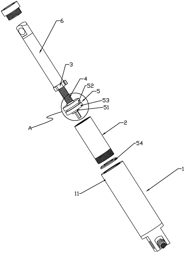
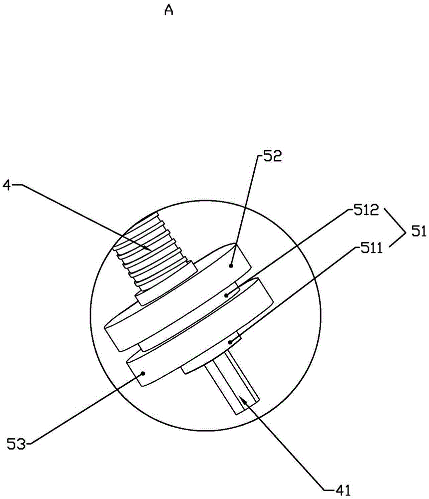
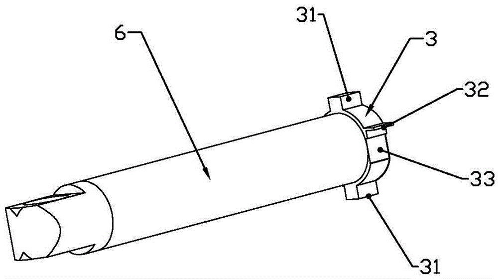
[0022] Such as Figures 1 to 5 As shown, a large-thrust linear electric push rod disclosed by the present invention includes a power unit 1, an electronic control unit, a transmission mechanism and a telescopic push rod 6, and the power unit includes a motor outer casing 11, a motor and a gear reducer (placed in The inside of the motor outer sleeve 11 is not shown, it is a conventional part of the electric push rod, so it will not be described in detail), the motor and the gear reducer are all placed in the motor outer sleeve 11, and the transmission mechanism includes a stroke sleeve 2, a nut 3, and a screw rod 4 And the bearing assembly 5, the nut 3 is screwed on the screw rod 4, the nut 3 is fixedly connected with the telescopic push rod 6, the nut 3 is dynamically fitted in the stroke sleeve 2 in an axially reciprocating sliding manner, and the telescopic push rod 6 follows the nut The movement of 3 realizes telescopic entry and exit of the stroke sleeve 2, the power input...


PUM


Abstract

The invention relates to a high thrust linear electric push rod, comprising a power device, an electronic control device, a transmission mechanism and a flexible push rod. The power device comprises a motor outer sleeve, and a motor and a gear reducer arranged in the motor outer sleeve; the transmission mechanism comprises a travel bushing, a nut, a screw and a bearing assembly; the nut is screwed on the screw through threads; the nut and the flexible push rod are fixedly connected; the nut dynamically matches in the travel bushing in an axial reciprocating slide mode; the flexible push rod stretches into or retreats from the travel bushing along with the moving of the nut; the power input end of the screw is in transmission connection with the power output end of the gear reducer; the power input end of the screw is born in the motor outer sleeve through the bearing assembly; the bearing assembly comprises a bearing base fixed on the screw; a pair of conical roller bearings is mounted on the bearing base; and the large ends of the pair of conical roller bearings are arranged oppositely. The high thrust linear electric push rod is advantaged by stable and reliable screw bearing, great axial bearing capability and great thrust.

Description

technical field [0001] The invention relates to a linear electric push rod and belongs to the technical field of a device for converting rotary motion into linear reciprocating motion. Background technique [0002] The electric push rod, also known as the linear drive, is an electric drive device that converts the rotational motion of the motor into the linear reciprocating motion of the push rod. Its working principle is that after the motor is decelerated by gears, it drives a pair of screw nuts. The rotary motion of the motor is changed into linear motion, and the push rod action is completed by using the forward and reverse rotation of the motor. [0003] Chinese Patent No. 201020525178.5 discloses "A Linear Electric Push Rod". Its main structure is, including electronic control device, power device, transmission mechanism and telescopic push rod. The power device includes the motor outer casing, motor and gear reducer. Tube (positioning sleeve 9 in the literature), n...

Claims


Application Information

Patent Timeline
Patent Type & Authority Applications(China)
IPC IPC(8): H02K7/06H02K5/173
CPCH02K5/173H02K7/06
Inventor 李洪
Owner WENZHOU GEMING TRANSMISSION EQUIP CO LTD
Learn More