Supercharge Your Innovation With Domain-Expert AI Agents!

Optical module test circuit, test device and coding test system

An optical module testing and testing device technology, which is used in transmission monitoring/testing/fault measurement systems, measurement devices, optical instrument testing, etc. , reduce production efficiency and other problems, to achieve the effect of reducing the probability of being scratched and damaged, improving the efficiency of code writing and testing, and simplifying the production process

Active Publication Date: 2018-01-23
SHENZHEN HI OPTEL TECH
View PDF5 Cites 0 Cited by
  • Summary
  • Abstract
  • Description
  • Claims
  • Application Information

AI Technical Summary

Problems solved by technology

[0004] (1) When the above-mentioned fixtures / tools used in the prior art are used, the pressing position is not easy to fix, and it is easy to cause scratches on the sheet metal cover of the optical module or the phenomenon that the pressing is not in place
[0005] (2) The turnaround time between the three different processes in the prior art is long, and manual pressing is easy to fatigue the operator and reduce production efficiency
[0006] (3) Since the existing fixture / tool ​​is made of metal or alloy, the relative displacement in contact with the sheet metal cover will easily cause the deformation of the sheet metal cover

Method used


Image

  • Optical module test circuit, test device and coding test system
  • Optical module test circuit, test device and coding test system
  • Optical module test circuit, test device and coding test system

Examples


Embodiment Construction

[0025] The present invention will be described in further detail below in conjunction with the accompanying drawings and embodiments.

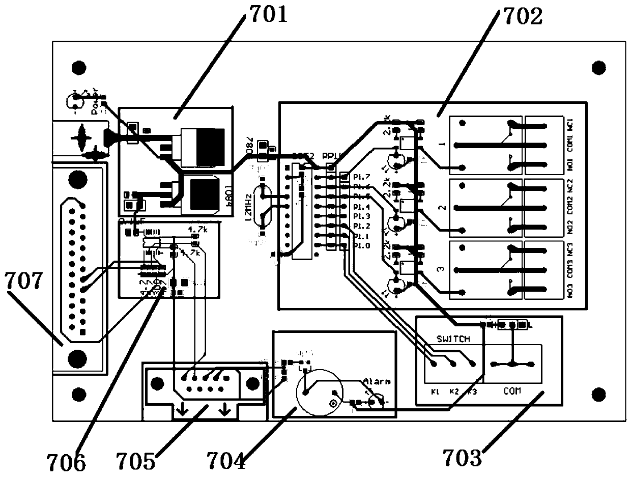
[0026] Such as figure 1 As shown, the optical module test circuit of the present invention includes a DC voltage stabilization unit 701, a power control unit 702, an external switch interface unit 703, a short circuit alarm unit 704, an optical module interface unit 705, a code writing unit 706, and a computer interface unit 707. The DC voltage stabilizing unit 701 supplies power for the optical module test circuit and the optical module 2, the power control unit 702 is respectively connected to the DC voltage stabilizing unit 701 and the external switch interface unit 703, and the short circuit alarm unit 704 is respectively connected to the external switch The interface unit 703 is connected to the optical module interface unit 705 , and the code writing unit 706 is connected to the computer interface unit 707 , the optical module interface ...


PUM


Abstract

The invention provides an optical module test circuit, a test device and a coding test system and belongs to the optical module test filed. The test device comprises a test base, a clamp, a connection module, a test circuit, a push module and a buckle press module. The test base is provided with a switch and a groove; the clamp is provided with a positioning groove; the connection module is fixedly connected with the clamp; the push module is used for pushing an optical module in the positioning groove and fixing the optical module in the test base; the buckle press module is used for pressing a buckle of a sheet metal cover of the optical module positioned in the test base; the connection module is used for connecting the optical module and the test circuit; and the test circuit is connected with the buckle press module and the push module. The beneficial effects are that the functions of automatic positioning and fixation of the optical module, automatic ground-housing short-circuit test, automatic coding and automatic sheet metal cover buckle pressing are realized; the production process is simplified; and loss due to long turnover time among processes is reduced.

Description

technical field [0001] The invention relates to the field of optical module testing, in particular to an optical module testing circuit, a testing device and a coding testing system. Background technique [0002] In the industry, there are three different operations for coding optical modules below 3G, pressing and snapping sheet metal covers, and short-circuiting tests between ground and housing. The coding of the optical module is to insert the optical module into the test socket, and input the serial number of the optical module into the software with a scanning gun; The buckle is pressed; the short circuit test between the ground and the shell is to manually insert the optical module into the test socket for testing. [0003] The prior art has the following deficiencies: [0004] (1) When the above-mentioned fixtures / tools used in the prior art are used, the pressing position is not easy to fix, and it is easy to cause scratches on the sheet metal cover of the optical ...

Claims


Application Information

Patent Timeline
Patent Type & Authority Patents(China)
IPC IPC(8): H04B10/07G01M11/02
CPCG01M11/0214H04B10/07
Inventor 揭志伟张小栋
Owner SHENZHEN HI OPTEL TECH
Features
  • R&D
  • Intellectual Property
  • Life Sciences
  • Materials
  • Tech Scout
  • Unparalleled Data Quality
  • Higher Quality Content
  • 60% Fewer Hallucinations
Learn More